Component supply apparatus
- Summary
- Abstract
- Description
- Claims
- Application Information
AI Technical Summary
Benefits of technology
Problems solved by technology
Method used
Image
Examples
first embodiment
[0042]In the following, description is made of a first embodiment of the present invention with reference to FIGS. 1 to 5.
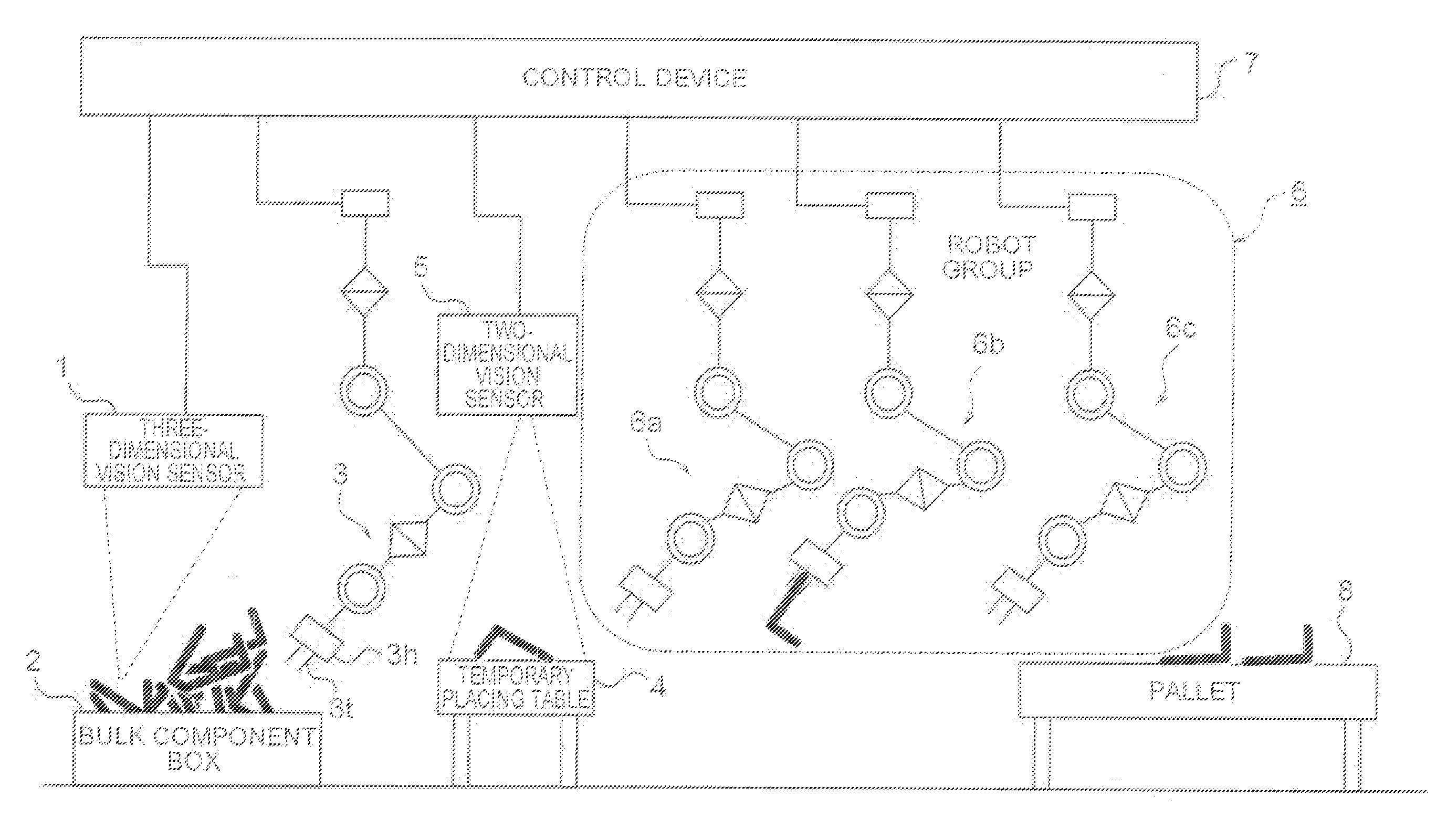
[0043]FIG. 1 is a schematic side view of an overall structure of a component supply apparatus according to the first embodiment of the present invention. Specifically, a plurality of (four) robots 3, 6a, 6b, and 6c are used to illustrate a structure for supplying bulk components in alignment.
[0044]In FIG. 1, the component supply apparatus includes a three-dimensional vision sensor 1, a bulk component box 2 for receiving a large number of components (for example, L-shaped components), the first robot 3 (hereinafter also simply referred to as “robot 3”) arranged close to the bulk component box 2, a temporary placing table 4 for the components, a two-dimensional vision sensor 5 for imaging the temporary placing table 4, a robot group 6 (second robot) including the robots 6a to 6c, a control device 7 for controlling the robot 3 and the robot group 6 based on detectio...
second embodiment
[0160]Note that, although not particularly referred to in the first embodiment (FIGS. 1 to 5) described above, there may be provided parameter optimization means for selecting an optimum parameter so as to maximize a rate of success in picking up the components in the bulk component box 2 at the time of the operation of the robot 3 relating to the three-dimensional vision sensor 1 and the control device 7.
[0161]In the following, with reference to FIGS. 1 to 4, description is made of a second embodiment of the present invention, in which the parameter optimization means is provided.
[0162]In the operation of the robot 3, there is an operation of, after operating the robot 3 so that a position and orientation of a lobe of a component and the positions and orientations of the claws 3t of the hand 3h of the robot 3 match each other, closing the claws 3t to grip the component.
[0163]At this time, it is necessary to control to what extent the opening width W between the claws 3t of the hand...
third embodiment
[0188]Note that, functions and features of the portions are not collectively referred to in the first or second embodiment described above. However, an advantage in alignment of the bulk components according to the present invention is obtained by the following first to fifth features (functions).
[0189]First, the first feature is that the depth map measuring means including the three-dimensional vision sensor 1 and the control device 7 is provided.
[0190]For example, in conventional apparatus, positions and orientations for gripping components are preset in accordance with respective component types. Meanwhile, the present invention has a function to flexibly change gripping positions and subsequent operations based on measurement data obtained through measurement with the three-dimensional vision sensor 1 immediately before the gripping operation without individual presetting.
[0191]Further, in the present invention, the measurement with the three-dimensional vision sensor 1, the two...
PUM
 Abstract
Description
Claims
Application Information
 - R&D
- Intellectual Property
- Life Sciences
- Materials
- Tech Scout
- Unparalleled Data Quality
- Higher Quality Content
- 60% Fewer Hallucinations
Browse by: Latest US Patents, China's latest patents, Technical Efficacy Thesaurus, Application Domain, Technology Topic, Popular Technical Reports.
© 2025 PatSnap. All rights reserved.Legal|Privacy policy|Modern Slavery Act Transparency Statement|Sitemap|About US| Contact US: help@patsnap.com


