Furnace including multiple trays and phase-change heat transfer

a technology of phase-change heat transfer and furnace, which is applied in the field of dryers, can solve the problems of difficult combustion system to use chemical energy in the gas combustion system (to create process heat) and place limits on the driving temperatur

Inactive Publication Date: 2014-05-29
WECHSLER MARK +3
View PDF1 Cites 3 Cited by
  • Summary
  • Abstract
  • Description
  • Claims
  • Application Information

AI Technical Summary

Benefits of technology

The present invention provides a method of torrefying material using a fluid that has a liquid and vapor phase. The method involves sequentially providing the material to trays at different vertical heights, condensing the vapor phase at a specific temperature, and then providing heat from this condensation to the material to torrefy it. The technical effect of this method is improved heat transfer through the material, resulting in faster and more uniform torrefaction.

Problems solved by technology

If the heat transfer medium is hot air, the risk of fire or partial combustion exists, placing limits on the driving temperature.
These limits may be overcome by either using an inert gas or oxygen depleted combustion gas as the heat transfer medium; however this leads to a more complicated system.
A combustion system to use the chemical energy in the gases (to create process heat) becomes problematic because of the low Btu value of the mixed gas.

Method used


Image

  • Furnace including multiple trays and phase-change heat transfer
  • Furnace including multiple trays and phase-change heat transfer
  • Furnace including multiple trays and phase-change heat transfer

Examples


second embodiment

[0036]Heat exchange fluid F is preferably a phase-change fluid that may be in either a vapor phase V or a liquid phase L. In one embodiment, heat exchange fluid F is DOWTHERM™ A (Dow Chemical Company, Midland, Mich.), an organic heat transfer fluid that is a eutectic mixture of biphenyl (C12H10) and diphenyl oxide (C12H10O). The saturated DOWTHERM™ A vapor has a temperature that ranges from 205° C. at 0.28 atmosphere, 260° C. at one atmosphere, and 305° C. at 2.6 atmospheres of pressure. In a second embodiment, heat exchange fluid F is a parafin fluid, ie. XCELTHERM® XT (Radco Industries, Batavia, Ill.). XCELTHERM® XT can be used for higher temperatures, as it has a higher temperature than DOWTHERM™ A at the same vapor pressure.

[0037]In one embodiment, the pressure PV within volumes 114 and 122 is maintained so that the temperature TV can achieve the proper temperature for material M within volume 112. Heater 100 may include diagnostics 155 that may be used to monitor the pressure a...

first embodiment

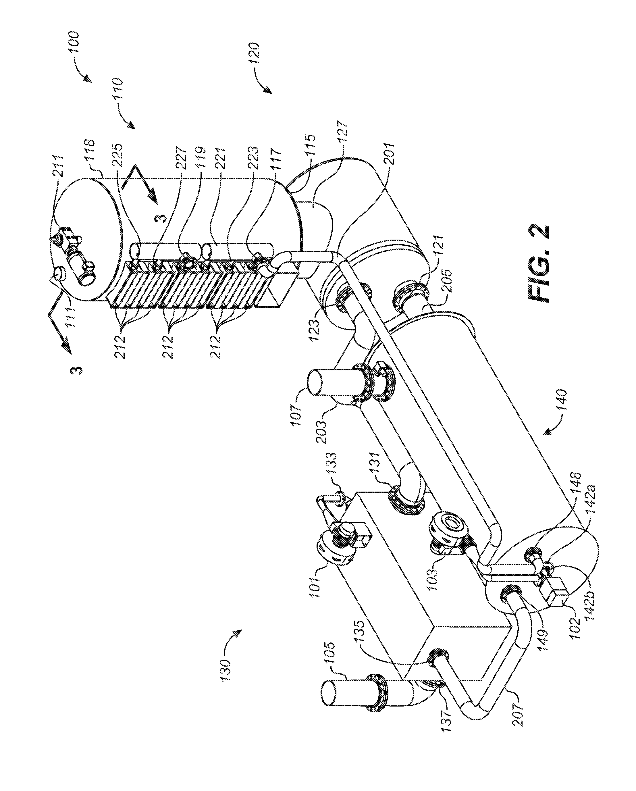
[0050]Details of heater 110 and vaporizer 120 are now described in greater detail, where FIG. 3 is a sectional view 3-3 of a first embodiment heater and vaporizer of FIG. 2, and FIG. 4 is a sectional view 4-4 of the heater and vaporizer of FIG. 3. As described subsequently in greater detail, heater 110 includes an alternating structure of volumes 112 and 114 to facilitate mixing of material M moving through volume 112 and heat transfer between material M and heat exchange fluid F. Paddle drive 211 is attached to a shaft 301 that also facilitates mixing of the material within volume 112.

[0051]Heater 120 is shown in greater detail in FIG. 5 as a detailed view of the heater of FIG. 3. Volume 112 includes horizontal trays 510 and 520, which form wall 116, and that are alternately arranged vertically and connected by vertical passageways 532, 534. Trays 510 and 520 are generally circular with an outer perimeter 511, 521, respectively, and centerline near or on a centerline C of shaft 301...


PUM


Abstract

A method and apparatus for heating materials is described. The apparatus is a furnace that includes multiple gravity-feed trays and a heat transfer fluid that heats material by the heat evolved during phase change. The apparatus also includes moving paddles that urge the material through each tray. The method provides for the torrefying of the material using a phase-change heat-transfer fluid by providing the material sequentially to at least two trays, where the at least two trays are substantially horizontal and disposed at different vertical heights; condensing the vapor phase at a temperature; and providing heat from the condensing the vapor phase to the material, where the temperature is sufficient to torrefy the material.

Description

CROSS-REFERENCE TO RELATED APPLICATIONS[0001]This application claims the benefit of U.S. Provisional Application No. 61 / 654,014, filed May 31, 2012, hereby incorporated by reference in its entirety.BACKGROUND OF THE INVENTION[0002]1. Field of the Invention[0003]The present invention generally relates to dryers, and more particularly to a method and system for drying solid material[0004]2. Discussion of the Background[0005]Existing dryers and roasters either transfer heat directly (when the heat transfer medium is in contact with and mixes with the process materials and products), or indirectly (when the heat exchange medium remains separated from the process materials and process products).[0006]The direct heating approach benefits from low thermal resistance and high surface area contact, often with high driving temperatures. If the heat transfer medium is hot air, the risk of fire or partial combustion exists, placing limits on the driving temperature. These limits may be overcome...

Claims


Application Information

Patent Timeline
IPC IPC(8): F26B21/08
CPCF26B21/08F26B17/003F26B21/145F26B23/00F26B2200/02F26B2200/24F26B3/20F26B3/22F26B23/022
Inventor WECHSLER, MARKWALL, CHADWHITNEY, JOHNHAMILTON, JIM
Owner WECHSLER MARK
Why Eureka
Try Eureka