
User Interface for Patient Risk Analysis System

a risk analysis and user interface technology, applied in the field of system and method of risk-based patient monitoring, can solve the problems of increasing complexity of medicine, increasing information avalanche, and clinicians being confronted with an avalanche of patient data

Inactive Publication Date: 2014-05-22
ETIOMETRY
View PDF8 Cites 17 Cited by
  • Summary
  • Abstract
  • Description
  • Claims
  • Application Information

AI Technical Summary

Benefits of technology

The patent describes a computer-implemented method for graphically communicating patient risks to a user. The method involves receiving data about multiple possible clinical states in which a patient may be classified, and displaying a plurality of graphical indicators on a screen. Each indicator represents the probability that the patient is in a specific clinical state at a given time. The indicators change dynamically based on user selections of specific points in time. The method can also include displaying information about the hazard levels associated with each indicator and allowing users to create tags to annotate the timeline. The technical effect of this invention is to provide a more intuitive and user-friendly way for healthcare professionals to communicate patient risks to patients.

Problems solved by technology

Practicing medicine is becoming increasingly more complicated due to the introduction of new sensors and treatments.
As a result, clinicians are confronted with an avalanche of patient data, which needs to be evaluated and well understood in order to prescribe the optimal treatment from the multitude of available options, while reducing patient risks.
One environment where this avalanche of information has become increasingly problematic is the Intensive Care Unit (ICU).
Not surprisingly, this leads to a large variance in hidden parameter estimation.
As an example, although numerous proxies for cardiac output are continuously monitored in critical care, studies have demonstrated poor correlation between subjective assessment by clinicians, and objective measurement by thermodilution.

Method used


Image

  • User Interface for Patient Risk Analysis System
  • User Interface for Patient Risk Analysis System
  • User Interface for Patient Risk Analysis System

Examples


Embodiment Construction

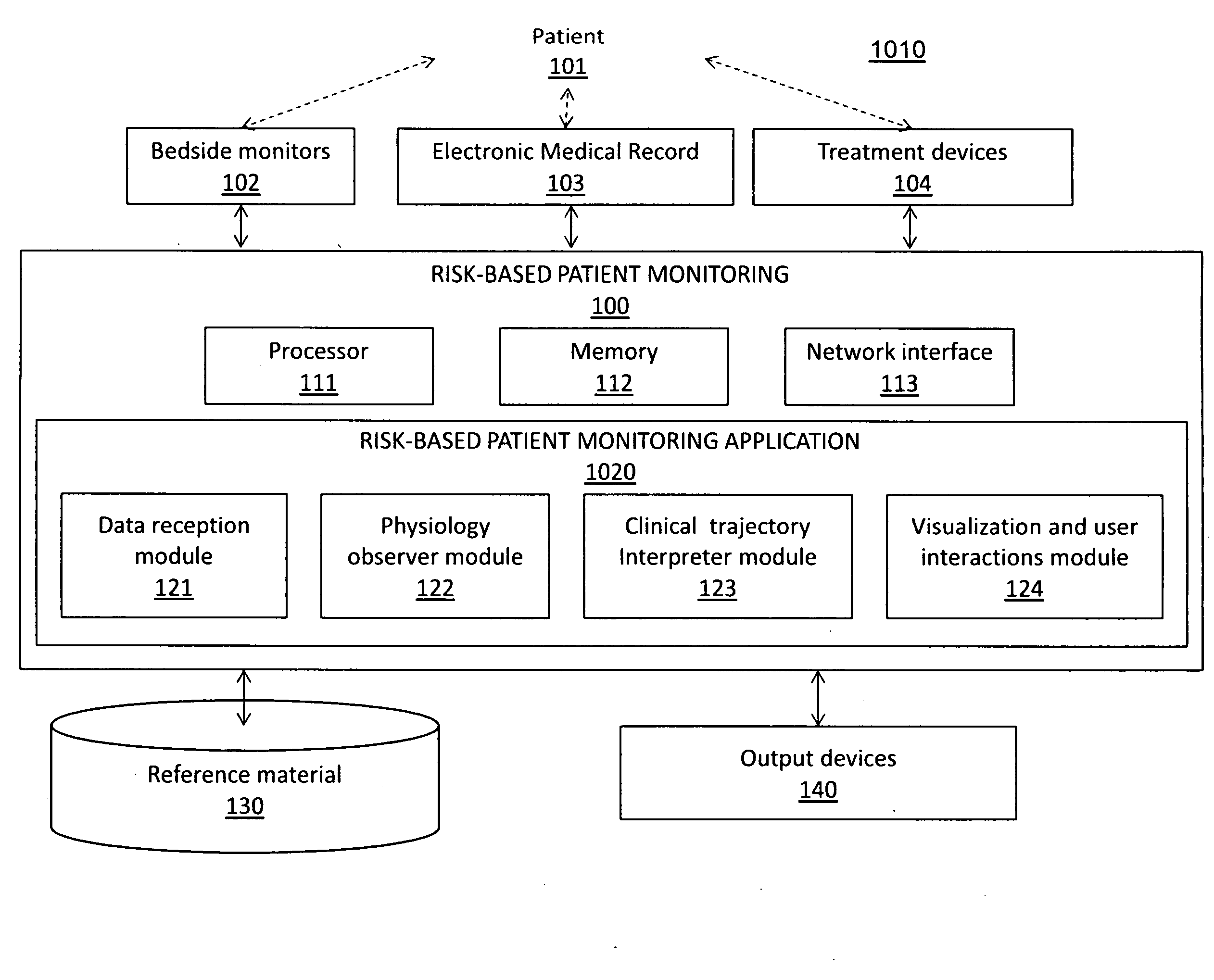
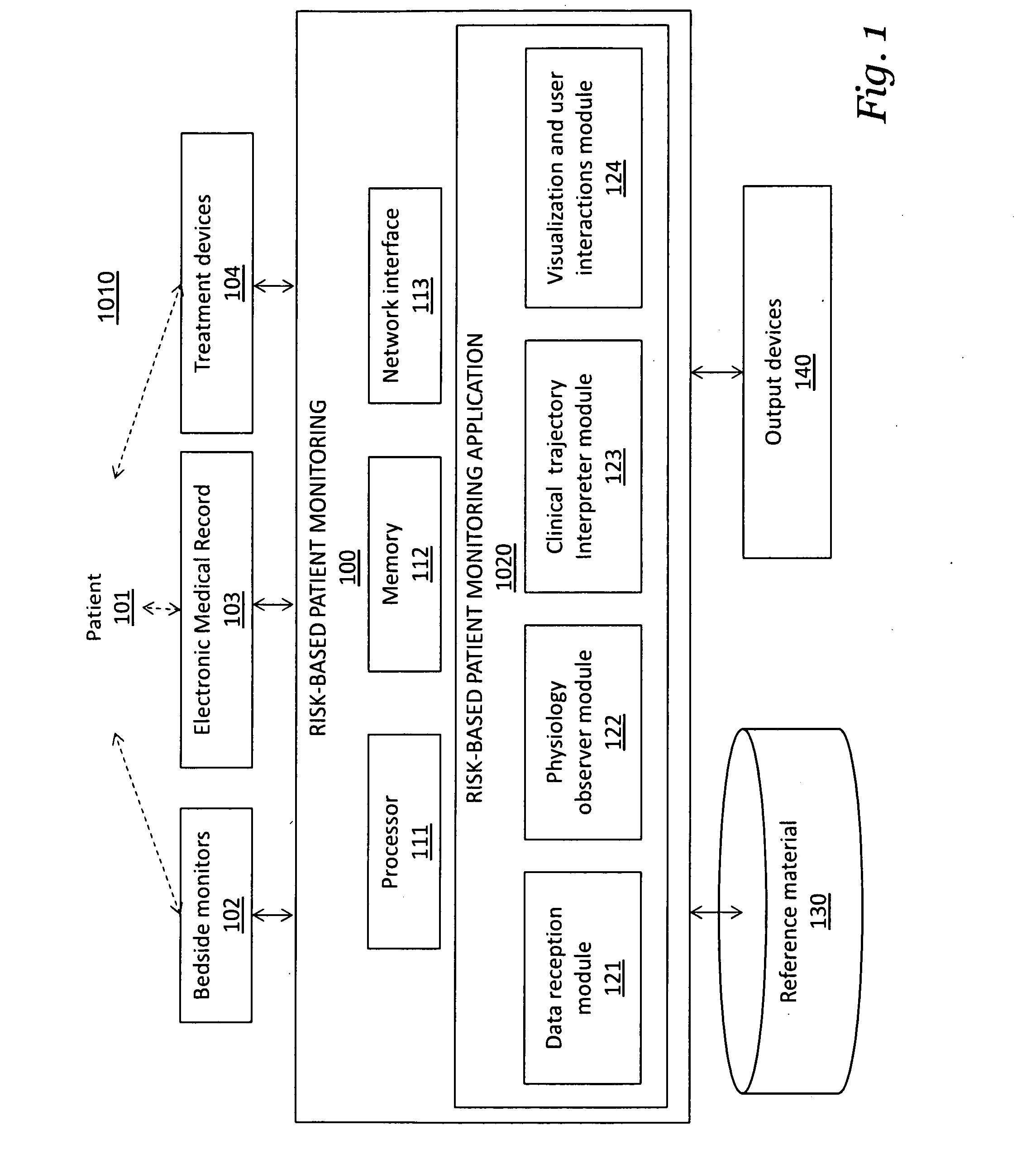
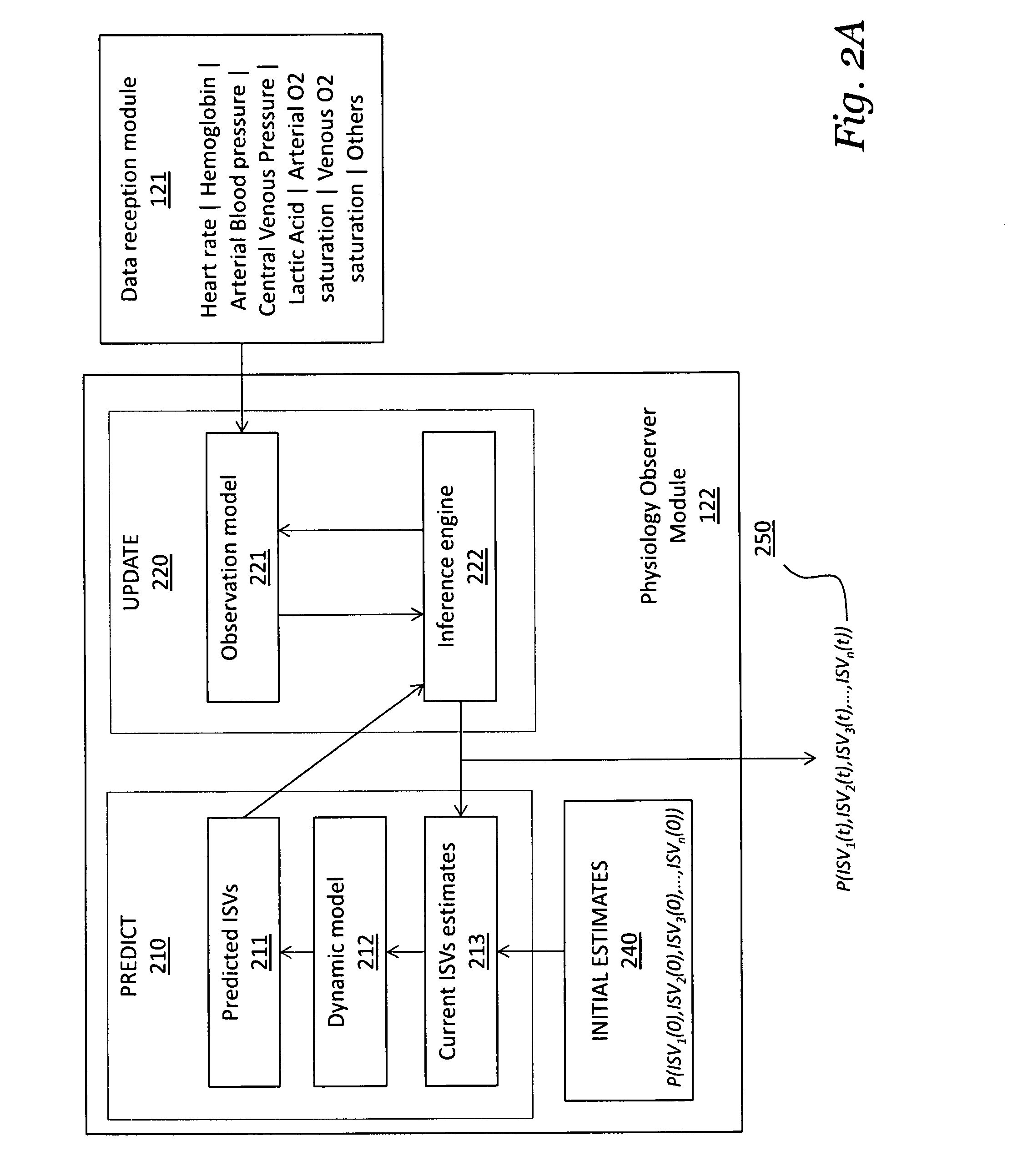
[0016]A first embodiment teaches a computer-implemented method of graphically communicating, to a user, patient risks for an individual patient, and includes the steps of receiving, from a device, data relating to a plurality of possible clinical patient states in which the patient may be classified; causing the display, on a display device, of a plurality of graphical indicators, each of the plurality of graphical indicators corresponding to one of the plurality of possible clinical patient states, each of the plurality of graphical indicators graphically identifying the probability that the patient is in a corresponding clinical patient state at a given point in a range of time, the plurality of graphical indicators configured to indicate a hazard level; and causing the display, on the display device, of a timeline controller configured to allow a user to dynamically select a plurality of points in time over the range of time, the graphical indicators changing dynamically in respo...


PUM


Abstract

A graphical user interface provides a system and method for representing patient risks and other clinical information. The risks correspond to the probabilities that the patient exhibits particular conditions and respective etiologies. In addition the graphical user interface provides a method for representing the utility of different possibly harmful modes of physiologic monitoring in estimating these risks.

Description

CROSS REFERENCE TO RELATED APPLICATIONS[0001]This application is a continuation of, and claims priority from, U.S. non-provisional patent application Ser. No. 13 / 826,441, filed Mar. 14, 2013 and entitled “Systems and Methods for Transitioning Patient Care from Signal-Based Monitoring to Risk-Based Monitoring, Attorney Docket No. 3816 / 1006, and also claims priority from U.S. provisional patent application Ser. No. 61 / 727,820, filed Nov. 19, 2012, entitled “User Interface Design for RAHM,” Attorney Docket No. 3816 / 1004; and[0002]U.S. provisional patent application Ser. No. 61 / 774,274, filed Mar. 7, 2013, entitled “Systems and Methods for Transitioning Patient Care from Signal-Based Monitoring to Risk-Based Monitoring,” Attorney Docket No. 3816 / 1002.[0003]Each of the foregoing applications is hereby incorporated herein by reference in their entirety.[0004]This application is also related to the following patent applications:[0005]U.S. non-provisional patent application Ser. No. 13 / 689,...

Claims


Application Information

Patent Timeline
Patent Type & Authority Applications(United States)
IPC IPC(8): G06F19/00
CPCG06F19/3431A61B5/14532A61B5/14542A61B5/14546A61B5/0205A61B5/7275G16H50/50G16H50/20G16H50/30A61B5/318
Inventor BARONOV, DIMITAR V.BUTLER, EVAN J.LOCK, JESSE M.
Owner ETIOMETRY
Learn More