Eureka AIR delivers breakthrough ideas for toughest innovation challenges, trusted by R&D personnel around the world.

Electrode-retaining headband

a technology of electrodes and headbands, applied in the field of electrodes retaining headbands, can solve the problems of lessening the definition of the electrical contact patch of the electrode, increasing the creep of the elastic bandage up and off the head, so as to achieve the effect of increasing comfor

Inactive Publication Date: 2014-05-22
NURALEVE
View PDF2 Cites 10 Cited by
  • Summary
  • Abstract
  • Description
  • Claims
  • Application Information

AI Technical Summary

Benefits of technology

The patent text describes a method for retaining electrodes on a patient's head for medical purposes. This is achieved by positioning a headband with straps on the head, inserting electrodes between the straps and the head, and mounting weights to bias the headband downwardly. The straps can be tightened or loosed for comfort. Additionally, the method may include referencing marking on the straps and headband to position the electrodes in accordance with an electrode placement system, or loosening the headband for increased comfort. Overall, the method ensures that the electrodes are securely and comfortably attached to the patient's head for accurate and safe medical purposes.

Problems solved by technology

The elastic bandage is susceptible to upward creep, as is it wrapped around a tapering part of the head and movement of the head results in movement, or creep, of the bandage up and off the head, due to the contracting force of the contracting elastic bandage.
The elastic bandage may also absorb liquid, which can result in a lessening of the definition of the electrical contact patch of the electrode, as the saline solution used in the sponge to transmit current from the electrode into the skin absorbs into the bandage and conducts current through the bandage.
The saline leak shunts the current from the intended electrode positioning to a position adjacent, inadvertently stimulating part of the brain that is not intended to receive stimulation, creating a short-circuit with the other electrode, or changing the density and distribution of current.
The application of electrodes and an elastic bandage is very difficult by one person as the electrode sponges must be held in position while the elastic bandage is wrapped around the head, and is normally performed with two people, the first holding the electrodes and the second wrapping the bandage.
This results in a time-consuming, awkward and inefficient process.
These variations have similar drawbacks such as difficult application and susceptibility to upward creep.
Although this counteracts the forces pulling the elastic bandage described above up and off the head by having a chin-holding component, the elastic material of the balaclava can shift during treatment unintentionally changing the placement of the electrodes and sponges.
Holes are made in the balaclava to permit placement of sponges, however these holes are permanent and their location cannot be altered.
Furthermore, any absorbent material in the balaclava may absorb the saline solution and unintentionally shunt the current through a different portion of the brain than targeted, or short-circuit one electrode to the other.
The balaclava may also be too warm and uncomfortable to wear in a clinic environment, as balaclavas are traditionally intended to keep head and neck warm during cold weather.
Retaining the sponge to the head poses a particular set of problems.
In other fields requiring electrode application to the head—such as electroencephalogram (EEG)—the electrodes do not deliver current to the patient, and thus most pre-existing electrode-head applications do not have the same concern for ensuring contact area to prevent skin burns.

Method used


Image

  • Electrode-retaining headband
  • Electrode-retaining headband
  • Electrode-retaining headband

Examples


Embodiment Construction

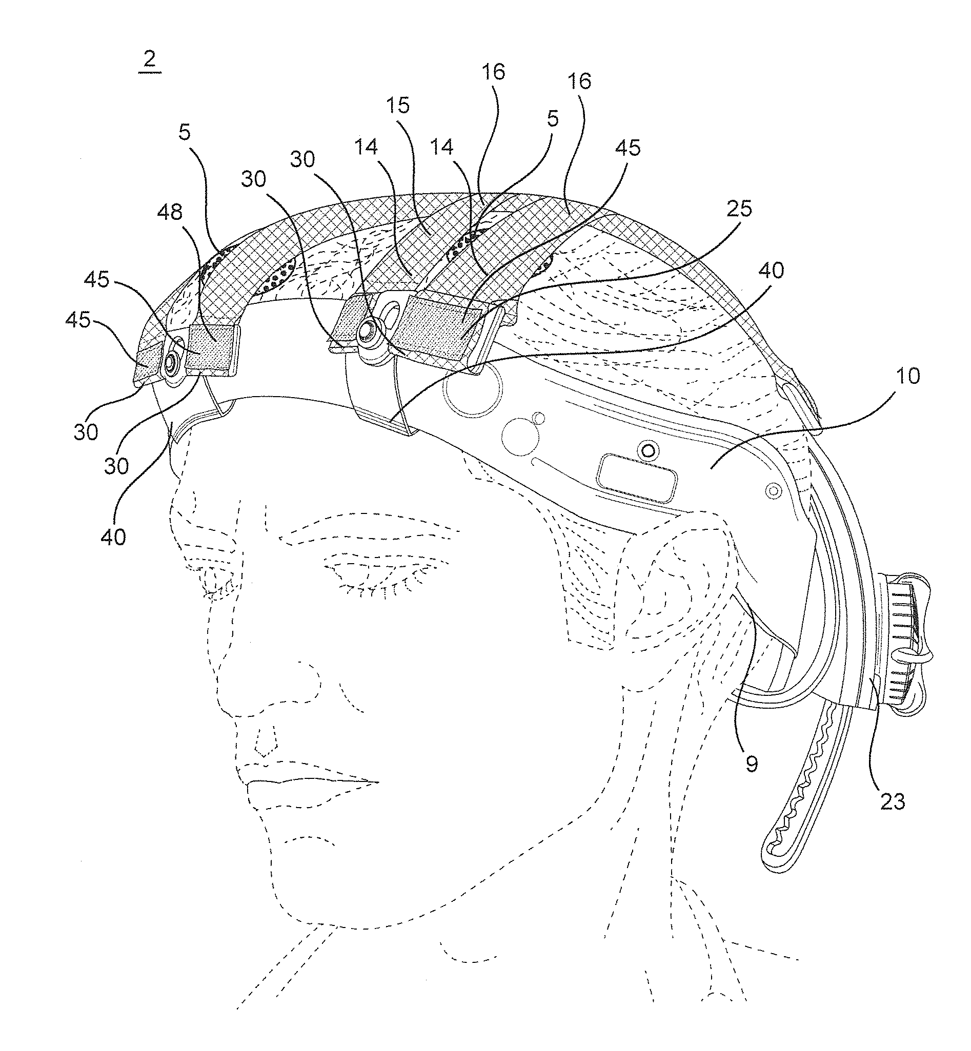
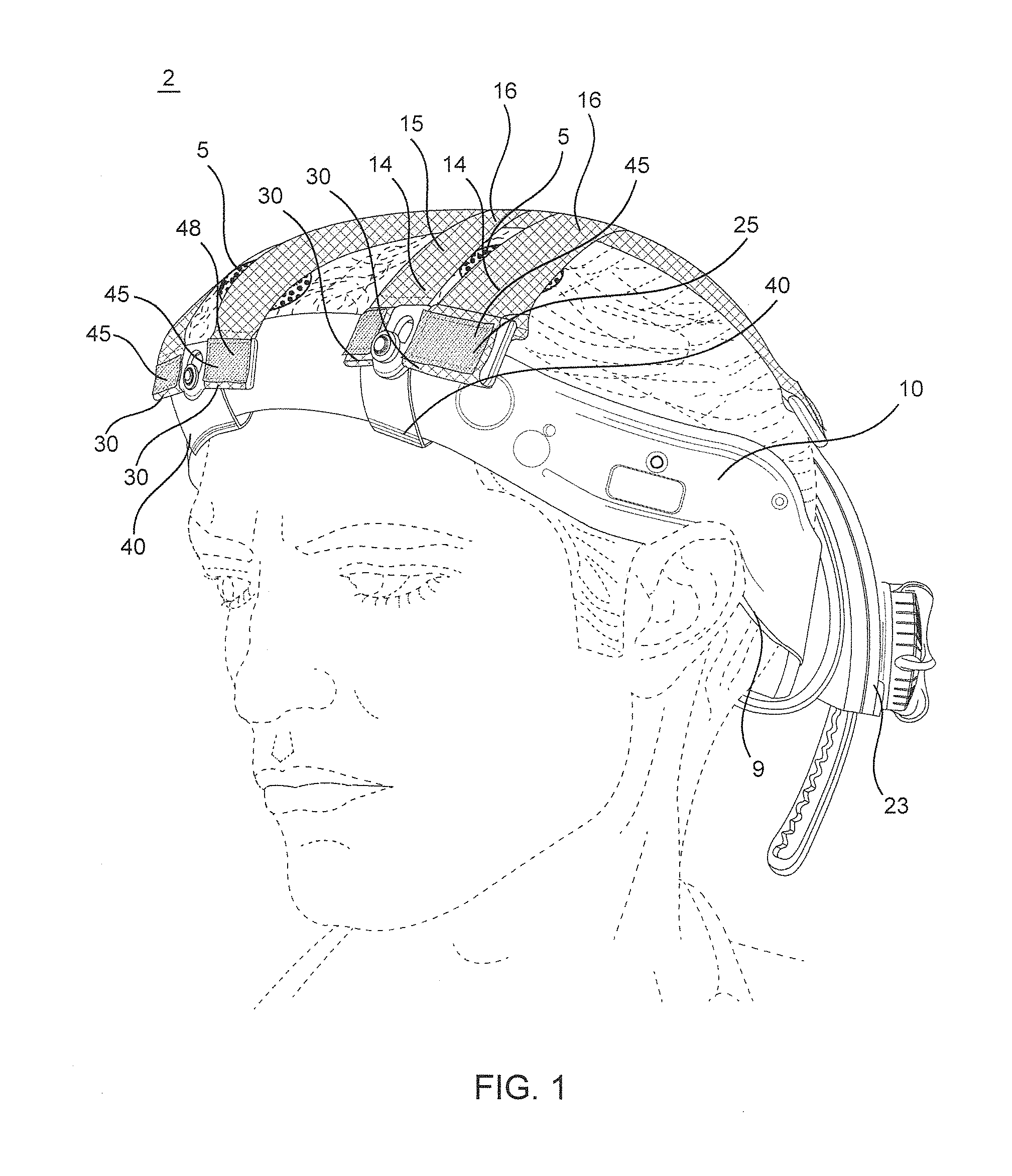
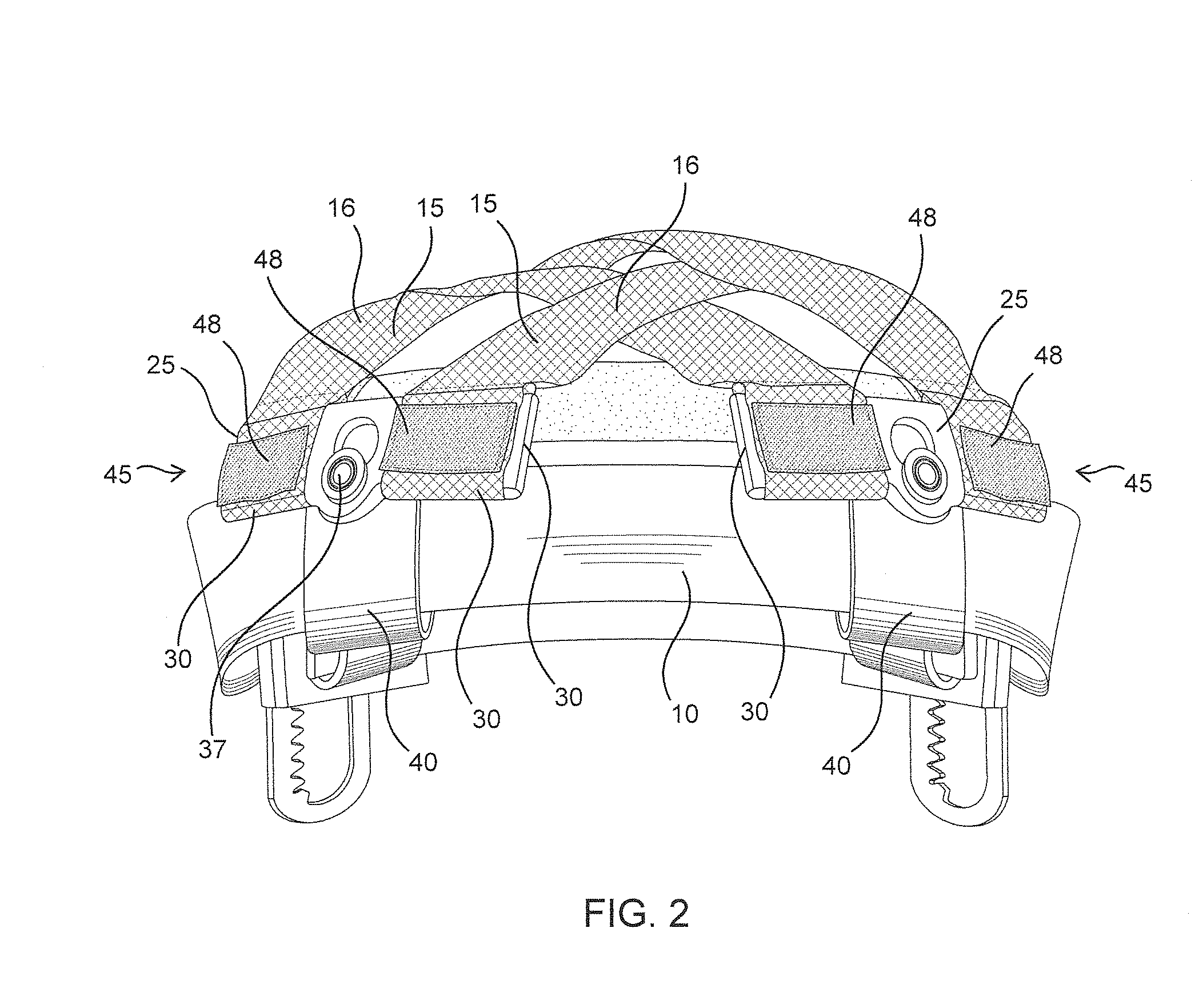
[0023]With reference to FIGS. 1, 3, 6 and 7, the electrode-retaining headband 2 consists of a main frame 10, adjustable and for mounting on the head of a patient, having one or more straps 15, each strap composed of one or more strips 16, each strap 15 connected at its ends 14 to opposite sides of the main frame 10 for retaining electrodes 5 against the head (shown in stippled lines). Each of the straps 15 is removably attached to approximately opposite sides of the frame 10 by curved supports 25. The frame fits more or less circumferentially around the head, from forehead to the rear of the cranium and above the ears at the side, and is adjustable for different head sizes by an adjustable mechanism 7 such as a gear mechanism, hook-and-loop fasteners, snaps or ratchets, as are known in the art for hats, hardhats, helmets and caps. The frame 10 may have a cushion 11 therein for contact with the forehead, as well as a rear cushion 12 for contact with the occipital area at the rear of ...


PUM


Abstract

A headband for retaining electrodes in position on a patient's head is disclosed, having an adjustable frame, straps for holding electrodes against the head, each strap fastened to the headband by an adjustable support, and the supports having weights removably coupled thereto such that gravity pulls the headband down against the electrodes. The headband may be used for transcranial electrical stimulation treatment or other treatment by electrodes. Further disclosed is a method of retaining electrodes on a patient's head, having the steps of positioning a headband having straps on the head, tightening the headband and straps, inserting electrodes between the straps of the headband and the head, mounting weights to bias the headband downwardly, and loosening the straps for greater comfort. The headband and straps may have markings to facilitate placement according to an electrode marking system.

Description

BACKGROUND OF THE INVENTION[0001]1. Field of the Invention[0002]The invention relates to a harness for the head, and in particular to a headband for retaining electrodes in position on a head.[0003]2. Description of the Prior Art[0004]The prevalence of Transcranial Stimulation devices and techniques has created a need for precise electrode placement on the head, wherein the electrodes may be positioned in a particular manner to target particular parts of the brain. The traditional solution to positioning electrodes and saline-soaked sponges uses an elastic bandage, which is wrapped around the head and over the positioned electrodes. The elastic bandage is susceptible to upward creep, as is it wrapped around a tapering part of the head and movement of the head results in movement, or creep, of the bandage up and off the head, due to the contracting force of the contracting elastic bandage. The elastic bandage may also absorb liquid, which can result in a lessening of the definition o...

Claims


Application Information

Patent Timeline
Patent Type & Authority Applications(United States)
IPC IPC(8): A61N1/04
CPCA61N1/0476A61N1/0484A61N1/0526A61N1/36014A61N1/36025A61N1/0456
Inventor GARDIN, PAULSHAPIRO, DANIELWILLIAMS, PATRICK D.H.BAILEY, KEVIN J.LEMAY, MATHIEUSHAUKAT, SHAZIBSHAPIRO, STANLEYDRESSLER, BRIAN
Owner NURALEVE
Why Eureka
Eureka Blog
Learn More