Laser ignition and misfire monitor

a misfire monitor and laser ignition technology, applied in the direction of engine starters, electric control, instruments, etc., can solve the problems of inefficiency of rpm-based methods at high rpm, inability to accurately detect misfires, and additional hardware costs and complexity, so as to increase the accuracy of misfire detection and improve the accuracy of information. the effect of speed and accuracy

Inactive Publication Date: 2014-05-15
FORD GLOBAL TECH LLC
View PDF16 Cites 7 Cited by
  • Summary
  • Abstract
  • Description
  • Claims
  • Application Information

AI Technical Summary

Benefits of technology

[0004]In one example, some of the above issues may be addressed by a method for an engine comprising: igniting air-fuel mixture in an engine cylinder with a laser ignition device and indicating a misfire based on an infrared sensor coupled to the cylinder. In this way, hardware available in an engine configured with a laser ignition system can be advantageously used to accurately identify engine misfire events.
[0006]In this way, it may be possible to take advantage of a laser ignition system to increase an accuracy of misfire detection. For example, such an approach may provide faster and more accurate information on when cylinder combustion occurred. By correlating cylinder information gathered by an infrared sensor with the timing of a laser ignition event, incomplete combustion due to a misfire can be identified. Accordingly, appropriate mitigating actions may be taken.

Problems solved by technology

The inventors herein have recognized that such misfire approaches may have limitations.
For example, RPM-based methods may be inefficient at high RPMs, particularly with high cylinder count engines.
The additional hardware adds component cost and complexity.
In addition, the location of the hardware in the severe environment of the exhaust system can lead to warranty issues.
Consequently, such approaches may cause inaccurate misfire detection under non-ideal vehicle operating conditions.
For example, RPM-based methods may inaccurately identify misfires when the vehicle is travelling on rough roads.
As another example, exhaust pressure-based methods may inaccurately identify misfires when there is frozen condensation in the sensor line.
However, if the temperature profile does not correspond to combustion, a misfire may be determined.

Method used


Image

  • Laser ignition and misfire monitor
  • Laser ignition and misfire monitor
  • Laser ignition and misfire monitor

Examples


Embodiment Construction

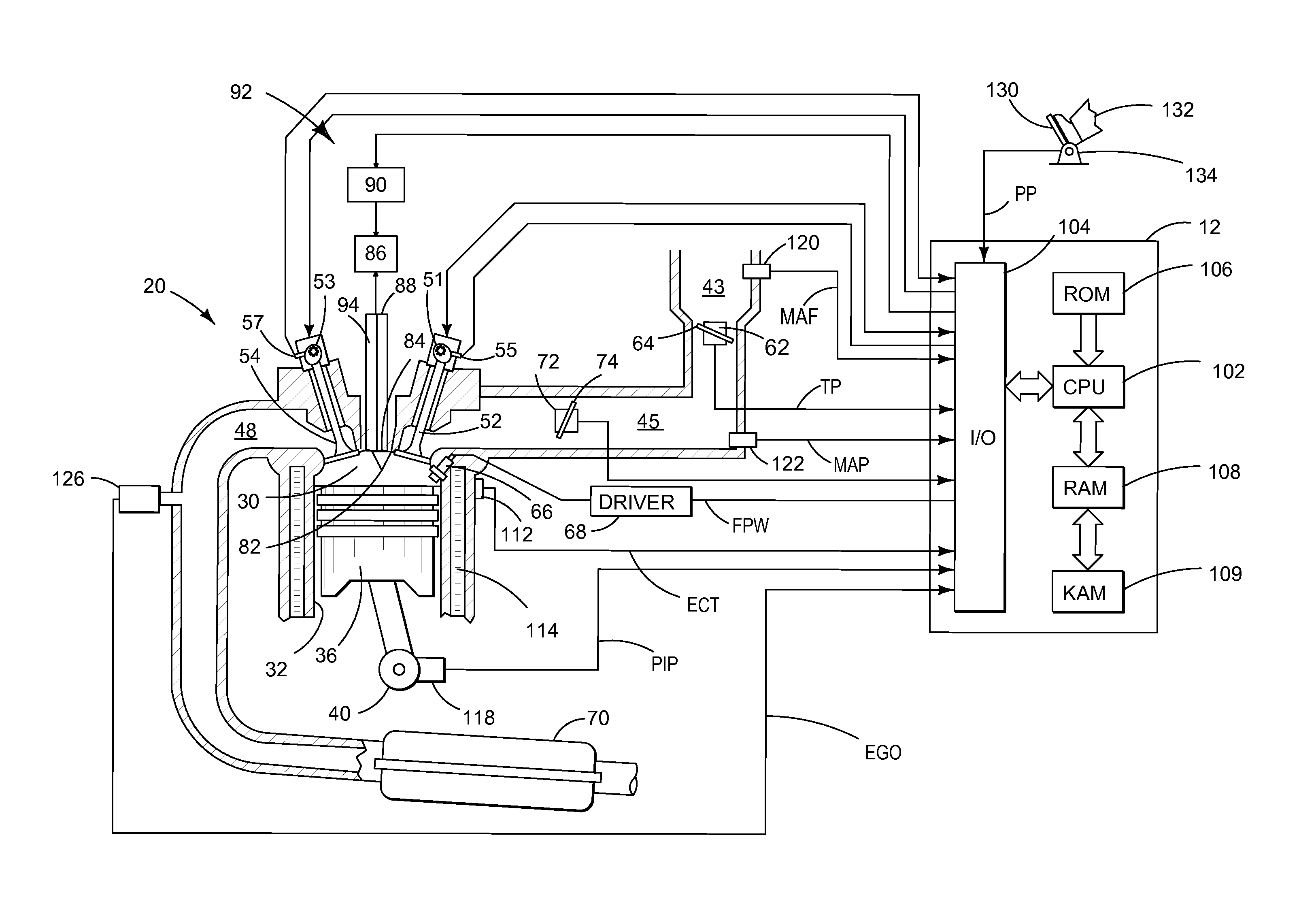
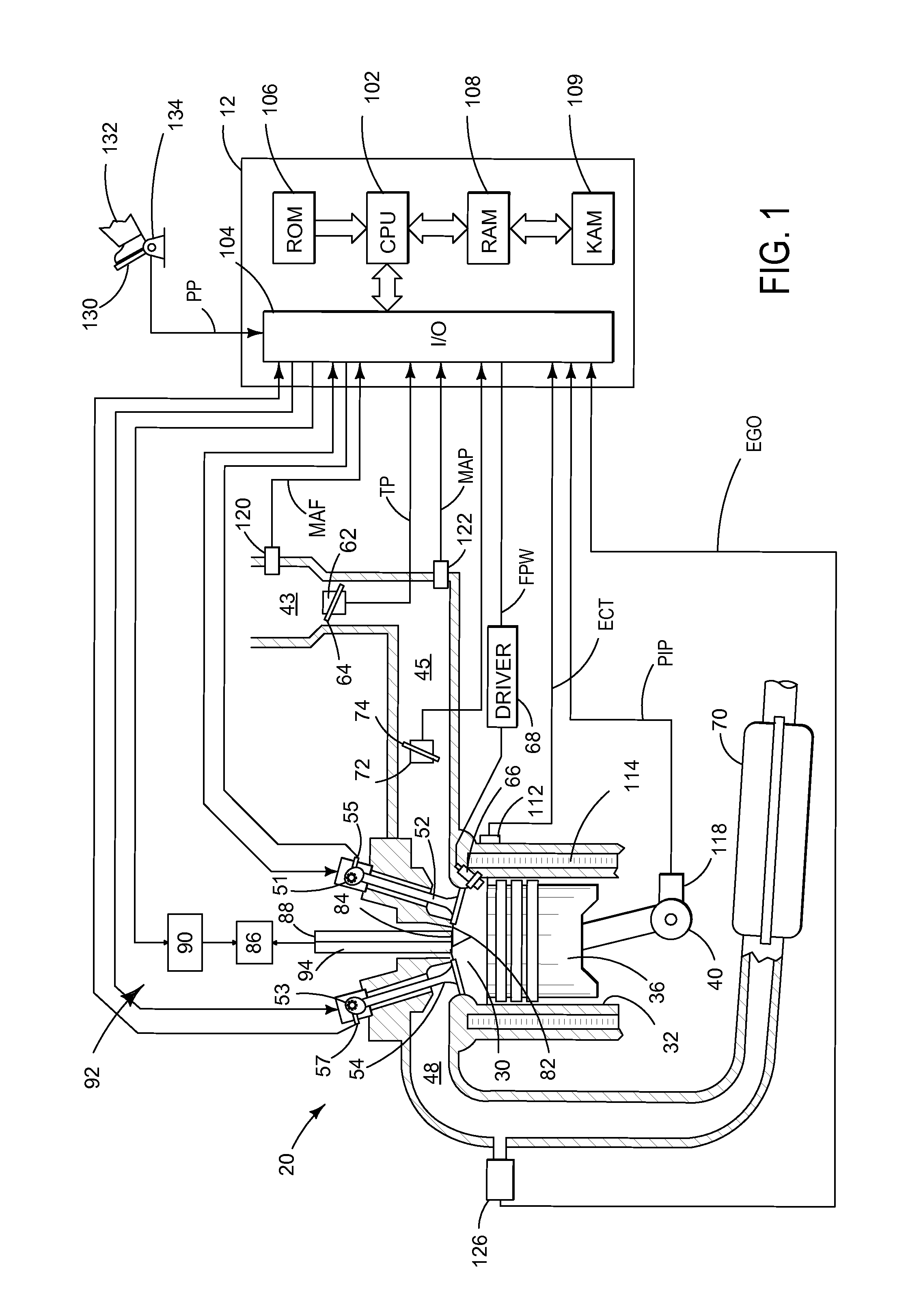
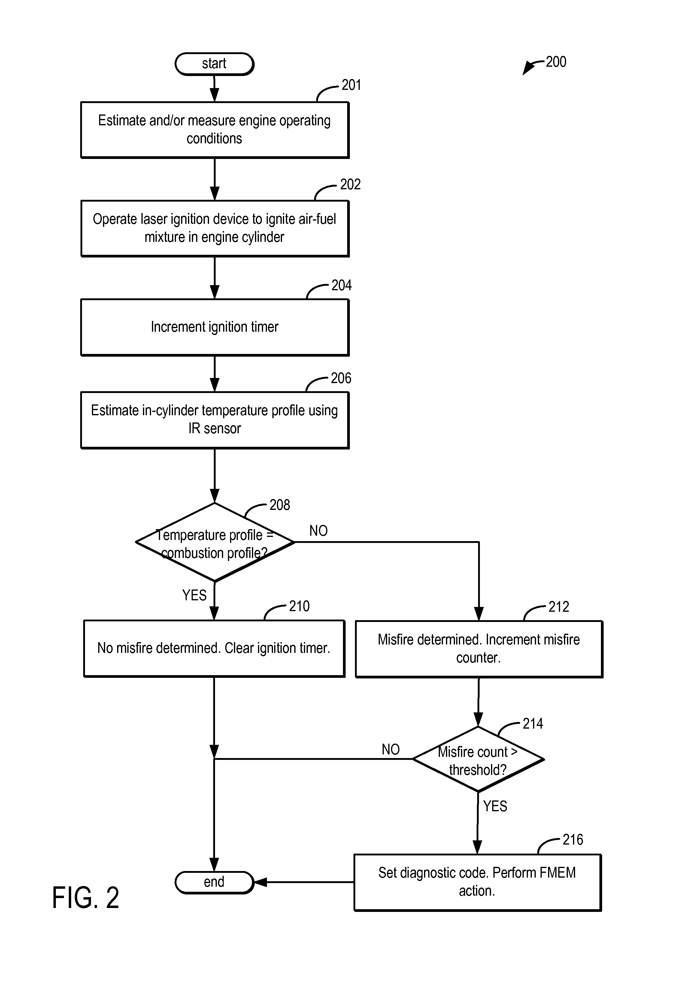
[0012]Methods and systems are provided for increasing an accuracy of misfire detection in an engine system configured with laser ignition, as shown in FIG. 1. An engine controller may be configured to perform a control routine, such as the routine of FIG. 2, to identify a misfire event based on an in-cylinder temperature profile following a laser ignition event. The in-cylinder temperature profile may be estimated by an infrared (IR) sensor coupled to the cylinder. The controller may also use an in-cylinder temperature profile estimated immediately before the laser ignition event to identify a cylinder pre-ignition event and differentiate abnormal combustion due to pre-ignition from those due to knock or misfire (FIG. 3). Example temperature profiles that may be used for diagnostics are shown at FIG. 4.

[0013]FIG. 1 shows a schematic diagram of an example cylinder of multi-cylinder internal combustion engine 20. Engine 20 may be controlled at least partially by a control system inclu...


PUM


Abstract

Systems and methods for increasing an accuracy of misfire detection are described. An infra-red sensor coupled to a cylinder is used to sense an in-cylinder temperature profile following a laser ignition event. A misfire event is identified based on a deviation of the sensed profile from an expected profile.

Description

BACKGROUND AND SUMMARY[0001]Engine control systems may include misfire detection modules for identifying combustion events that occur outside of a base ignition timing. As one example, misfires may be detected using RPM-based methods wherein torque pulses are correlated with crankshaft speed. As another example, misfires may be detected based on exhaust pressure wherein exhaust pressure pulses are correlated with crankshaft speed.[0002]The inventors herein have recognized that such misfire approaches may have limitations. For example, RPM-based methods may be inefficient at high RPMs, particularly with high cylinder count engines. This is because in engines with a high cylinder count, each individual ignition event covers a smaller arc of the engine rotation before the next event takes place. Consequently, even a single misfire event in a high cylinder count engine may be muted by the next ignition event occurring much sooner during the rotation of the engine. For example, a 1-cylin...

Claims


Application Information

Patent Timeline
Patent Type & Authority Applications(United States)
IPC IPC(8): G06F19/00F02D45/00
CPCF02D45/00G06F19/00F02P5/152F02P5/1527F02P23/04F02D35/022F02D35/025F02D35/026F02D35/027F02D2200/1015Y02T10/40F02N15/10
Inventor MARTIN, DOUGLAS RAYMONDMILLER, KENNETH JAMES
Owner FORD GLOBAL TECH LLC
Why Eureka
Try Eureka