
Ethernet fault management systems and methods

a fault management system and fault management technology, applied in the field of network operation, administration and maintenance (oam) systems and methods, can solve the problems of loss of continuity, high cost of flexibility, and inability to implement deep packet inspection for handling variable packet formats and tlv objects, etc., and achieve the effect of reducing the number of locations

Active Publication Date: 2014-05-15
CIENA
View PDF7 Cites 31 Cited by
  • Summary
  • Abstract
  • Description
  • Claims
  • Application Information

AI Technical Summary

Benefits of technology

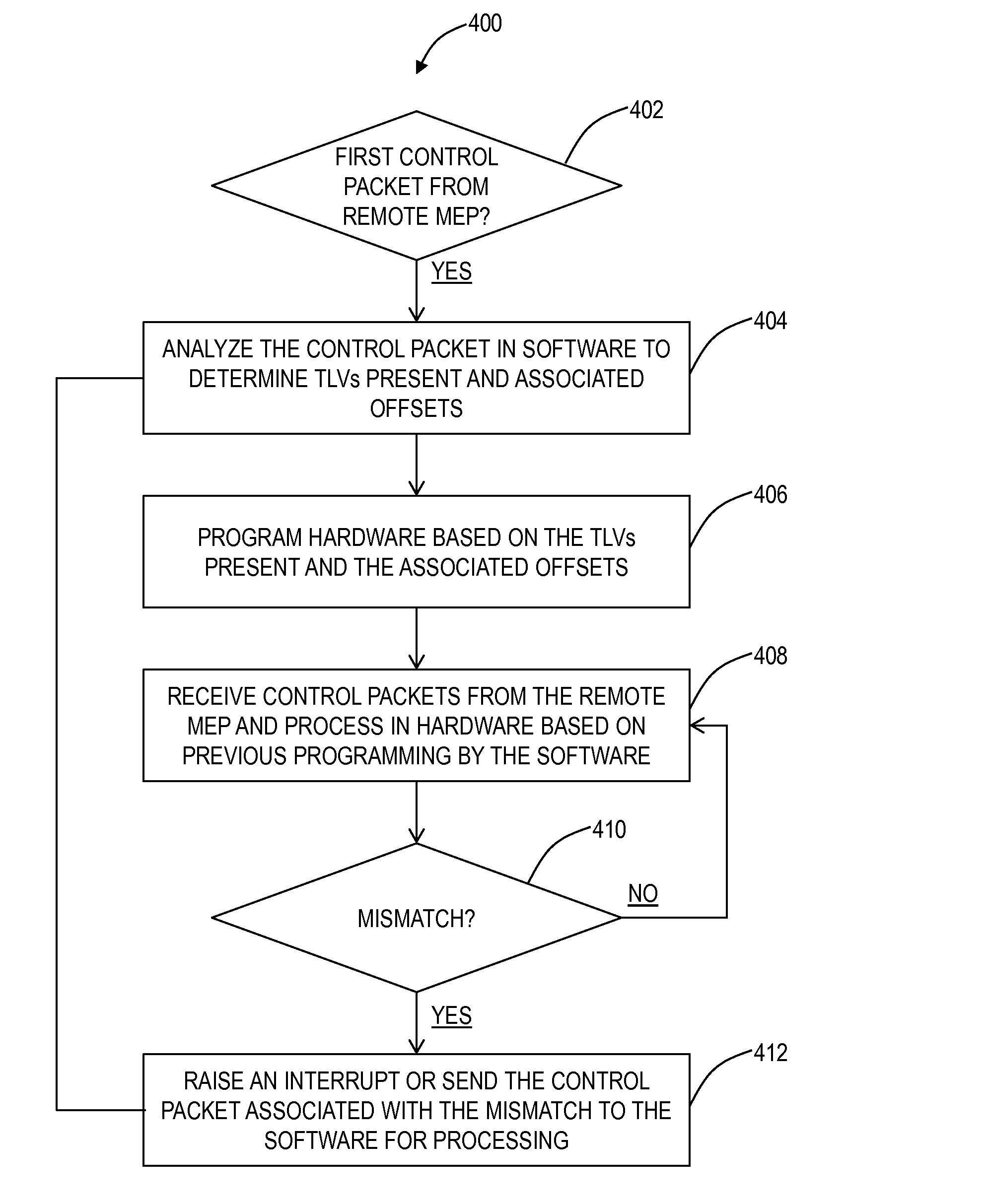
The patent describes a method for managing faults in an Ethernet network using software and hardware devices. The method involves analyzing control packets to determine objects and their associated offsets, programming the hardware device based on these objects, and processing subsequent control packets in the hardware device. The method can detect and isolate mismatches and determine the presence of a Link Aggregation Group (LAG) in which the port participates. The technical effects of the patent include improved fault management in Ethernet networks and improved efficiency in detecting and isolating mismatches.

Problems solved by technology

Software-based features and support have advantages of flexibility, i.e. protocol support can be easily updated, changed, added, etc., but disadvantages of processing efficiency and speed.
Hardware-based designs provide processing efficiency and speed but at the expense of flexibility.
Specifically, a challenge in hardware-based fault management is that deep packet inspection for handling variable packet formats and TLV objects is expensive and difficult to implement.
Additionally, another challenge associated with hardware-based fault management includes handling fault detection on Link Aggregation Group (LAG) ports spread across multiple devices.
Disadvantageously, this approach is inefficient when a receive port of the LAG changes, the OAM protocol manager may generate false Loss of Continuity (LOC) alarms and disrupt the service.
Problematically, OAM cannot be configured in hardware-based designs on LAG ports spread across multiple devices since each device is monitoring Continuity Check Messages (CCMs) separately.

Method used


Image

  • Ethernet fault management systems and methods
  • Ethernet fault management systems and methods
  • Ethernet fault management systems and methods

Examples


Embodiment Construction

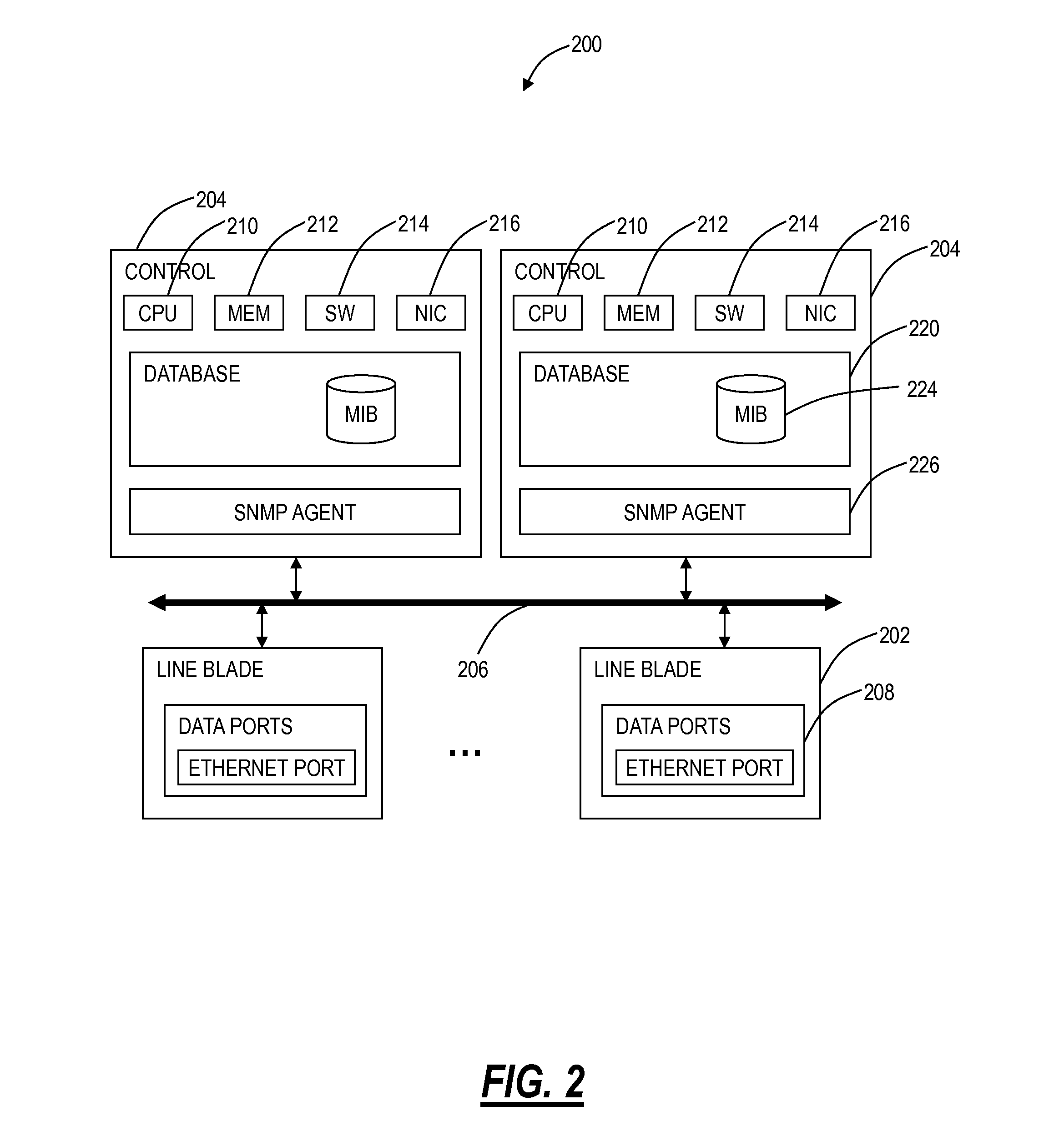
[0016]In various exemplary embodiments, Ethernet fault management systems and methods using programmable TLV offsets combine software-based OAM protocol support with hardware-based fault management support to delegate generation and processing of OAM protocol messages to hardware devices with the software-based protocol support used to program hardware based on fixed offsets in the OAM protocol messages. The hardware can be designed to be flexible since the hardware can be agnostic to the logic within the OAM protocol which would reside in the software. The Ethernet fault management systems and methods combine the flexibility of software-based approaches with the speed and efficiency of hardware-based approaches. Also, the systems and methods provide a mechanism to handle extensibility of the OAM protocols, thus future proofing the hardware. Similarly, the systems and methods can speed up support for new TLV objects as required in the hardware.

[0017]Specifically, the systems and met...


PUM


Abstract

Ethernet fault management systems and methods using programmable Type-Length-Value (TLV) offsets combine software-based Operations, Administration, and Maintenance (OAM) protocol support with hardware-based fault management support to delegate generation and processing of OAM protocol messages to hardware devices with the software-based protocol support used to program hardware based on fixed offsets in the OAM protocol messages. The hardware can be designed to be flexible since the hardware can be agnostic to the logic within the OAM protocol which would reside in the software. The Ethernet fault management systems and methods combine the flexibility of software-based approaches with the speed and efficiency of hardware-based approaches.

Description

FIELD OF THE INVENTION[0001]Generally, the field of art of the present disclosure pertains to networking Operations, Administration, and Maintenance (OAM) systems and methods, and more particularly, to Ethernet fault management systems and methods using programmable Type-Length-Value (TLV) offsets.BACKGROUND OF THE INVENTION[0002]Carrier Ethernet is evolving to support the needs of the carrier network environment. Carrier Ethernet requires scalable, reliable, and dynamic mechanisms to support operations, administration, and management (OAM) and traffic engineering (TE). Standards have been developed in the Metro Ethernet Forum (MEF), International Telecommunication Union (ITU), Institute of Electrical and Electronics Engineers (IEEE), and the like providing many of these required extensions. Specifically, Connectivity Fault Management (CFM) is an Ethernet standard to provide many common OAM functions associated with underlying network transport for services. For example, CFM is defi...

Claims


Application Information

Patent Timeline
Patent Type & Authority Applications(United States)
IPC IPC(8): H04L12/24
CPCH04L41/0672H04L41/0681H04L41/0661H04L43/028H04L43/0811
Inventor JADAV, ASHEESHGORDON, CORY D.JOSHI, MADHAVI R.JETTI, VENKATA SATYA MAHESHKUKKADAPU, SRI SIRI VINEELAFROMM, KELLY D.
Owner CIENA
Learn More