Multilevel electronic power converter

a power converter and multi-level technology, applied in power conversion systems, ac-d ac network circuit arrangements, etc., can solve the problems of high cost, large size, excessively complicated and expensive electromechanical design, etc., and achieve the effect of achieving the size, design, cost, operation, and control. and attainable levels

Active Publication Date: 2014-05-15
INGETEAM POWER TECH
View PDF6 Cites 14 Cited by
  • Summary
  • Abstract
  • Description
  • Claims
  • Application Information

AI Technical Summary

Benefits of technology

[0016]From this configuration it results that the intermediate semiconductors, which are connected at one end to the intermediate DC voltage terminal and at the other end to the intermediate terminal of the internal branch, are introduced in the n-level converter of the present invention. These new intermediate semiconductors introduced allow a distinct operation of the converter, providing redundancies that can be used so that the output current of the converter only circulates through one of the capacitors connected between the positive branch and the negative branch, such that the size of the rest can be reduced and solving the problem of the converter described in EP0555432A1. A first preferred embodiment comprises n−1 first external controlled semiconductors and n−1 second external controlled semiconductors. A second preferred embodiment comprises n−3 internal controlled semiconductors. The first preferred embodiment and the second preferred embodiment can be used together. Thus, for n voltage levels of the n−1 capacitors that would be connected between the positive and negative branches, only (n−3) / 2 of the capacitors must be sized for all the output current of the converter, whereas (n+1) / 2 of the capacitors would aid in fixing the cut-off voltage of the semiconductors and will be of help in the switching dead times. An electronic power converter with n or more levels in the output voltage with a reduced number of high-current capacitors and semiconductors is thereby obtained.
[0024]The controlled semiconductors of the converter according to the present invention can be controlled by means of a PWM (pulse-width modulation) strategy which allows synthesizing an alternating voltage in the AC terminal by means of a pulse-width modulation control system to synthesize an alternating voltage in the AC terminal. In addition, to keep the voltage of the intermediate DC terminal and the voltage of each of the high-current DC capacitors stable, the converter can be provided with a voltage stabilizing system using redundancies available in output voltage vectors of the converter. To reduce the losses in the converter and thus increase the efficiency of the system, the semiconductors closest to the DC bus could be semiconductors having low conduction losses, such as, for example IGCT, GTO type semiconductors, etc., since these will switch to the frequency of the fundamental AC.
[0026]As inferred from the above, the present invention achieves its objective by means of a converter which reduces the number of high-current capacitors to less than half, and it has considerable advantages in its size, design, cost, operation, control and attainable levels.

Problems solved by technology

A large amount of multilevel conversion topologies like those described in patent documents EP0555432A1, EP1051799B1, EP1673849A1, EP1815586A1, EP2080262B1, is known in the state of the art even though most of them involve an excessively complicated and expensive electromechanical design.
However, this converter has the problem of having a large size and high cost which greatly complicates the electromechanical design.
The need of this large size limits the number of levels attainable by this converter since there will come a time when the volume required makes it non-viable.
The main problem of the converter described in EP1051799B1 is that in order to obtain an n-level converter, it is necessary to serialize (n−1) / 2 controlled semiconductors.
The main problem that this converter has is that in switches there are parasitic inductances causing unwanted voltage surges such that it reduces the current capacity and the service life of the semiconductors.
These additional elements increase the cost and size and they add complexity to the converter.
These additional semiconductors also increase the cost and size and they add complexity to the converter.

Method used


Image

  • Multilevel electronic power converter
  • Multilevel electronic power converter
  • Multilevel electronic power converter

Examples


Embodiment Construction

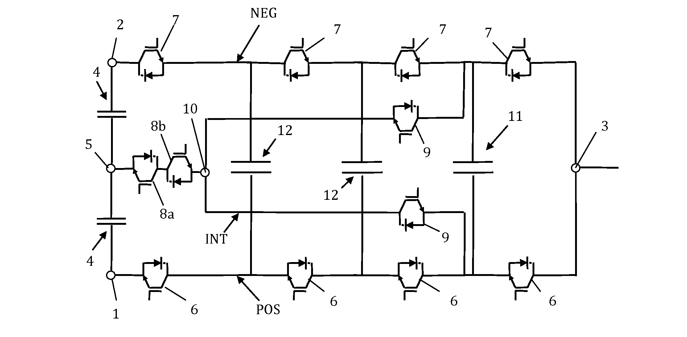
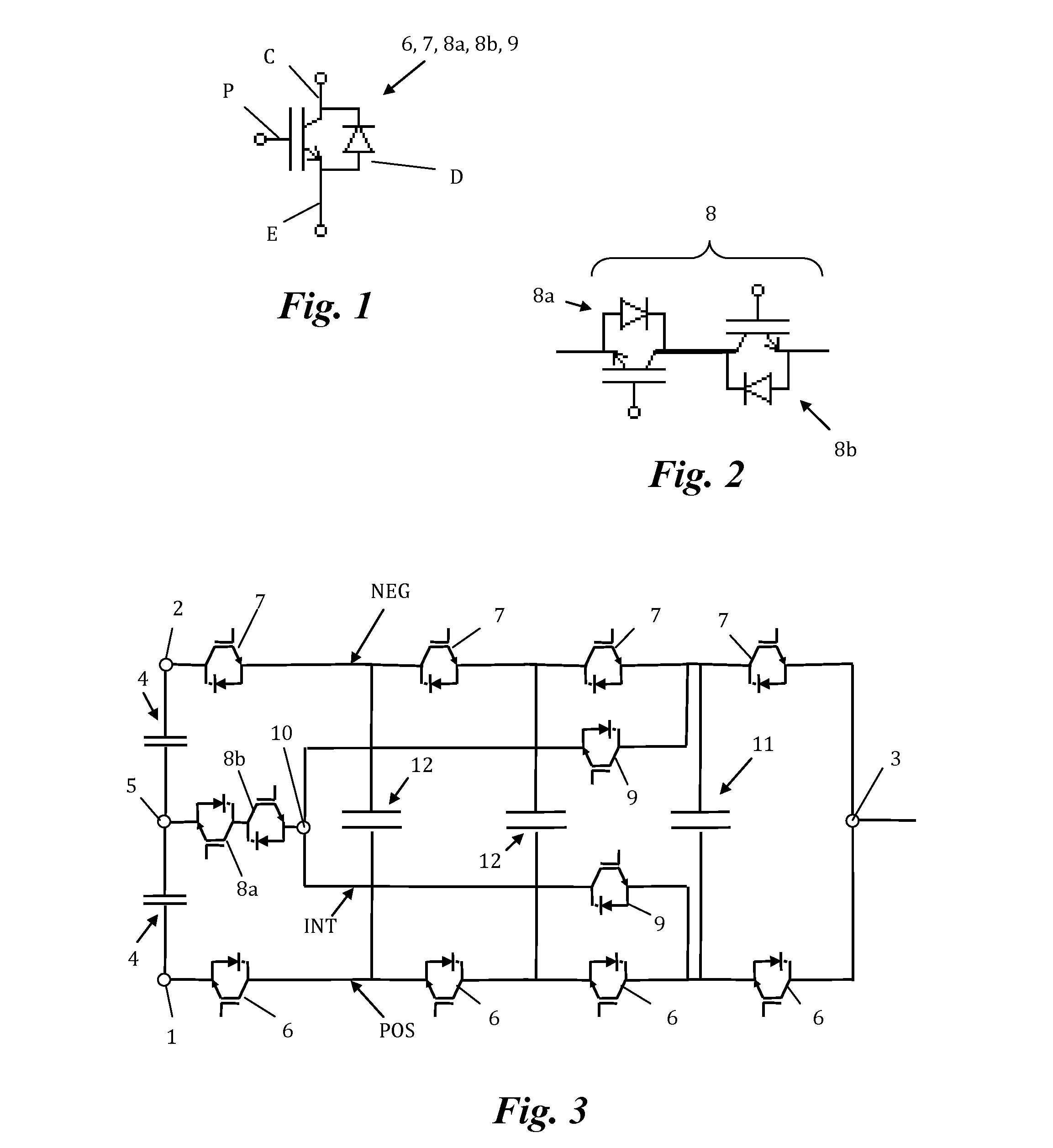
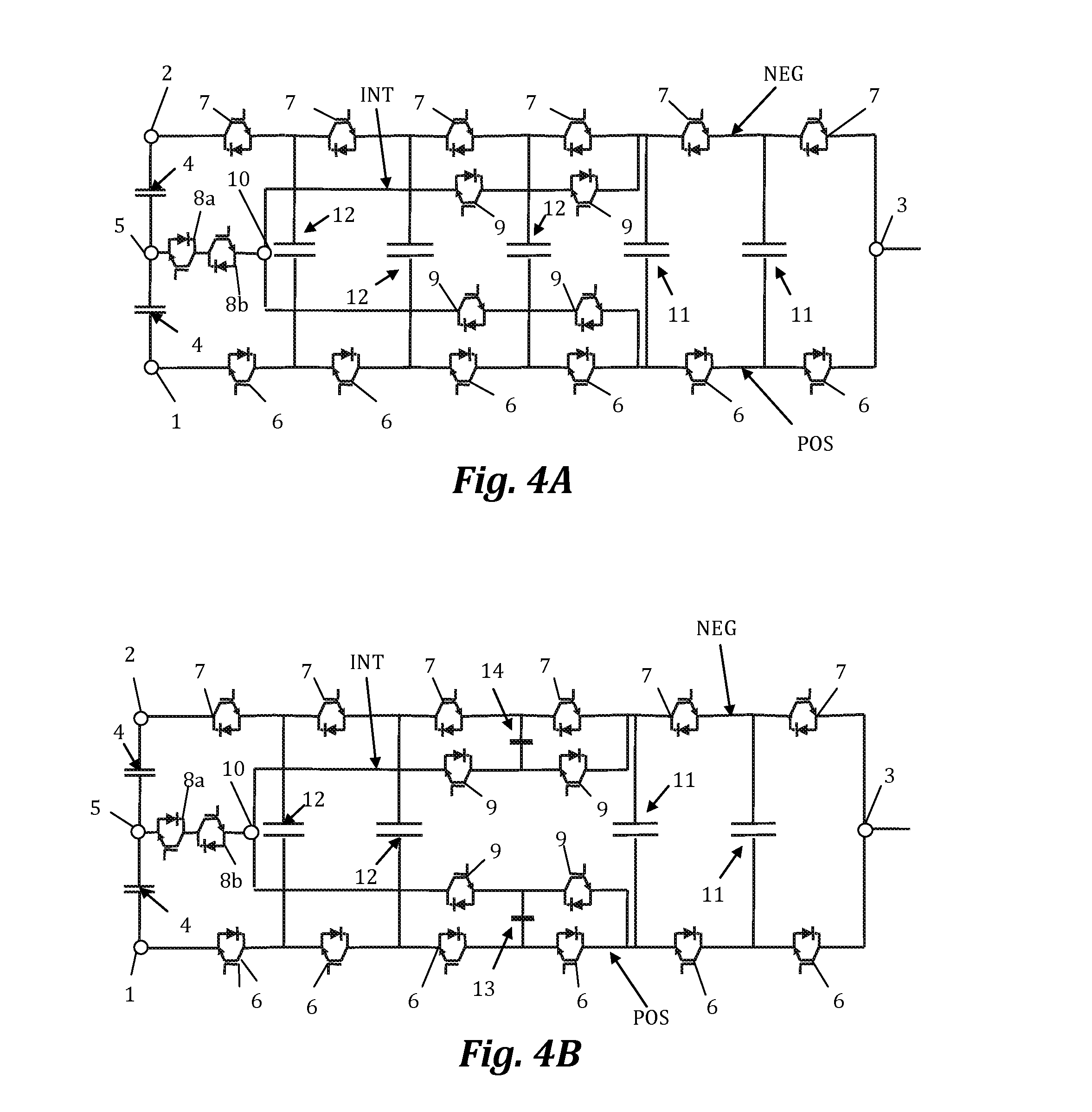
[0010]The object of the present invention is to overcome the drawbacks of the state of the art detailed above by means of a multilevel electronic DC / AC or AC / DC power converter for n output voltage levels with

[0011]a positive branch with a positive DC voltage terminal, a negative branch with a negative DC voltage terminal, and an AC voltage terminal connected to the positive branch and to the negative branch; at least two DC bus capacitors interconnected between the positive DC voltage terminal and the negative DC voltage terminal, and an intermediate DC voltage terminal connected between the two DC bus capacitors; a plurality of first external controlled semiconductors with antiparallel diodes connected in series in the positive branch between the positive DC voltage terminal and the AC voltage terminal, and a plurality of second external controlled semiconductors with antiparallel diodes connected in series in the negative branch between the negative DC voltage terminal and the AC...


PUM


Abstract

The invention relates to a multilevel electronic power converter for n output voltage levels witha positive branch (POS) with a positive DC voltage terminal (1), a negative branch (NEG) with a negative DC voltage terminal (2), and an AC voltage terminal (3) connected to the positive branch (POS) and to the negative branch (NEG);at least two DC bus capacitors (4) interconnected between the positive DC voltage terminal (1) and negative DC voltage terminal (2) and an intermediate DC voltage terminal (5) connected between the two DC bus capacitors (4);at least two first external semiconductors (6) and at least two second external semiconductors (7) with respective antiparallel diodes connected in series, respectively, in the positive (POS) and negative (NEG) branches between the DC voltage terminal (1, 2) and the AC voltage terminal (3);at least one high-current DC capacitor (11) connected between the positive (POS) and negative (NEG) branches, and at least two high-frequency low-current capacitors (12, 13, 14) connected between the positive (POS) and negative (NEG) branches;an internal branch (INT) connected in parallel with each high-current DC capacitor (11) comprising at least two internal semiconductors (9) with antiparallel diodes connected in series between them and to an intermediate terminal (10);at least one intermediate semiconductor (8) formed by two controlled semiconductors with antiparallel diodes and connected in anti-series, connected between the intermediate DC voltage terminal (5) and the intermediate terminal (10).

Description

TECHNICAL FIELD OF THE INVENTION [0001]The present invention is comprised in the technical field of electronic power converters with a plurality of levels in the output voltage and high current-carrying capacity.BACKGROUND OF THE INVENTION [0002]Electronic converters are widely used in power-generating applications, such as, for example in wind power generators. The desired requirements of a converter include obtaining an output current with the best THD (Total Harmonic Distortion) possible and obtaining a high voltage to minimize conduction losses.[0003]Today, most manufacturers of electronic conversion stages are trying to increase the power thereof by increasing the number of voltage levels in the output voltage. This not only increases the power used but it also improves the quality of the current delivered, greatly reducing the harmonic content.[0004]The two previous objectives can be achieved by means of using multilevel converters. These converters are capable of working with...

Claims


Application Information

Patent Timeline
Patent Type & Authority Applications(United States)
IPC IPC(8): H02J4/00
CPCH02J4/00H02M7/483H02M7/487H02M1/0095H02M7/4837
Inventor ZABALETA MAEZTU, MIKELLOPEZ TABERNA, JES SBURGUETE ARCHEL, EDUARDO
Owner INGETEAM POWER TECH
Why Eureka
Try Eureka