
Reducing perceived brightness of illumination light source in electro-optical readers that illuminate and read targets by image capture

an electro-optical reader and illumination light source technology, applied in the direction of instruments, photoelectric discharge tubes, sensing by electromagnetic radiation, etc., can solve the problems of sluggish reading performance, delay in decoding, and component lifetime degradation,

Active Publication Date: 2014-05-15
SYMBOL TECH LLC
View PDF4 Cites 4 Cited by
  • Summary
  • Abstract
  • Description
  • Claims
  • Application Information

AI Technical Summary

Benefits of technology

The present disclosure relates to an apparatus and method for illuminating and reading targets using a solid-state imaging reader without causing brightness issues or distracting operators. The technical effect of the invention is to reduce the perceived brightness of the illumination light source, while still effectively reading the targets. Previous solutions, such as continuous or periodic activation of the imaging scan engine, have resulted in sluggish performance, slow decoding, and distracting flashing light. The invention proposes a method of illuminating and reading targets only when they are in the reading field of view, thereby reducing the energy waste and improving the operator's experience.

Problems solved by technology

However, continuous, repetitive, flashing of bright intense light from the LEDs of the illuminating light system consumes and wastes energy, degrades component lifetimes, and can be perceived as bothersome, distracting and annoying to the operators of the readers and to nearby consumers being served.
However, this creates sluggishness in the reader's performance and delays in decoding, which can be perceived as an engineering defect.
However, under low ambient light conditions, for example, when a reader is located in a dark corner in a retail environment, the activation time will be slow since the exposure of the image sensor has to be very long in order to acquire an image of acceptable brightness for object detection.
Again, the reader's performance is sluggish.
Although generally satisfactory for its intended purpose, the use of an object sensing system is disadvantageous, because a portion of the IR light incident on the window of the workstation is reflected therefrom back into the object detection field of view of the object sensor.
This reflected portion of the IR light creates undesirable hot spots in the object detection field of view and may significantly compromise object sensor performance.

Method used


Image

  • Reducing perceived brightness of illumination light source in electro-optical readers that illuminate and read targets by image capture
  • Reducing perceived brightness of illumination light source in electro-optical readers that illuminate and read targets by image capture
  • Reducing perceived brightness of illumination light source in electro-optical readers that illuminate and read targets by image capture

Examples


Embodiment Construction

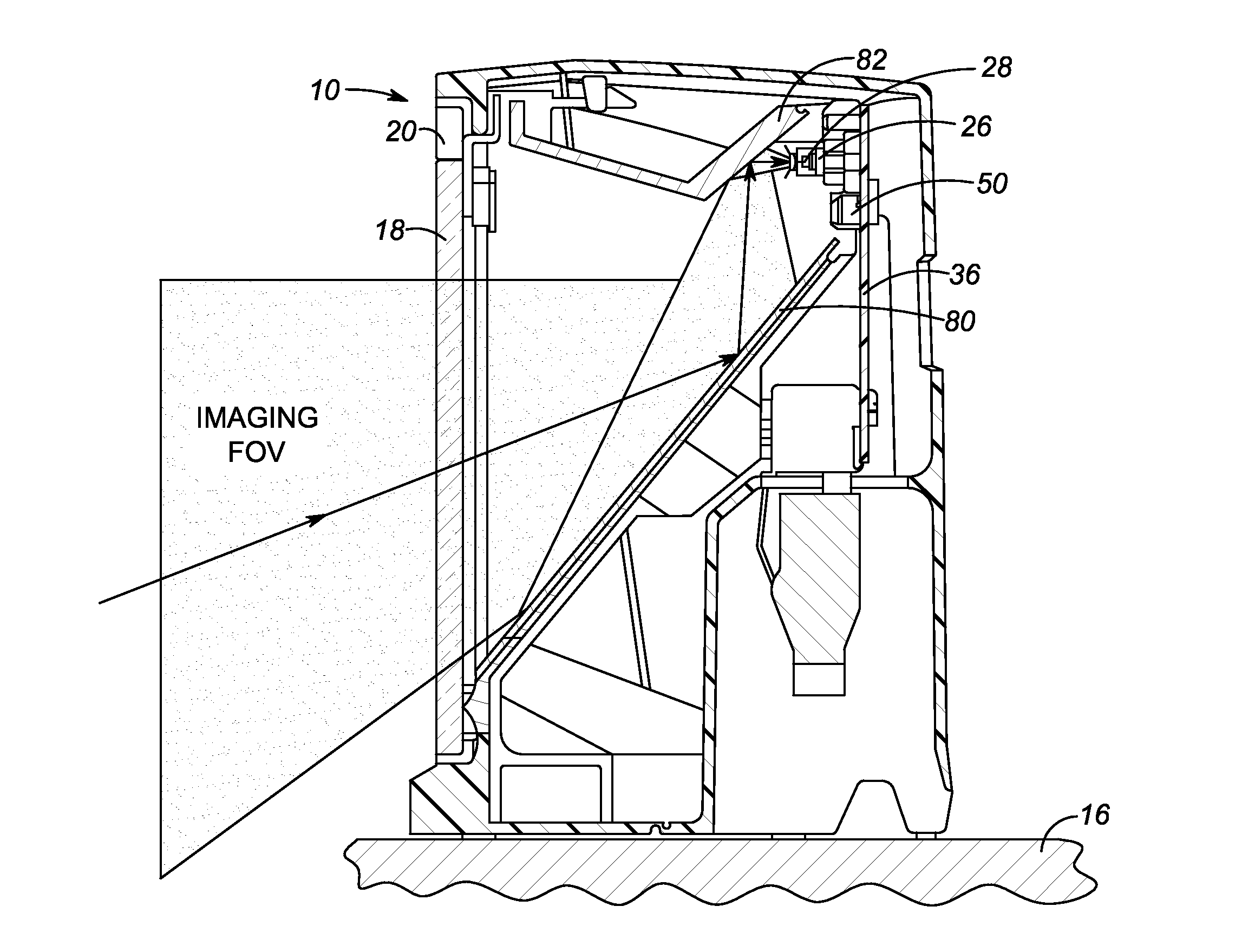
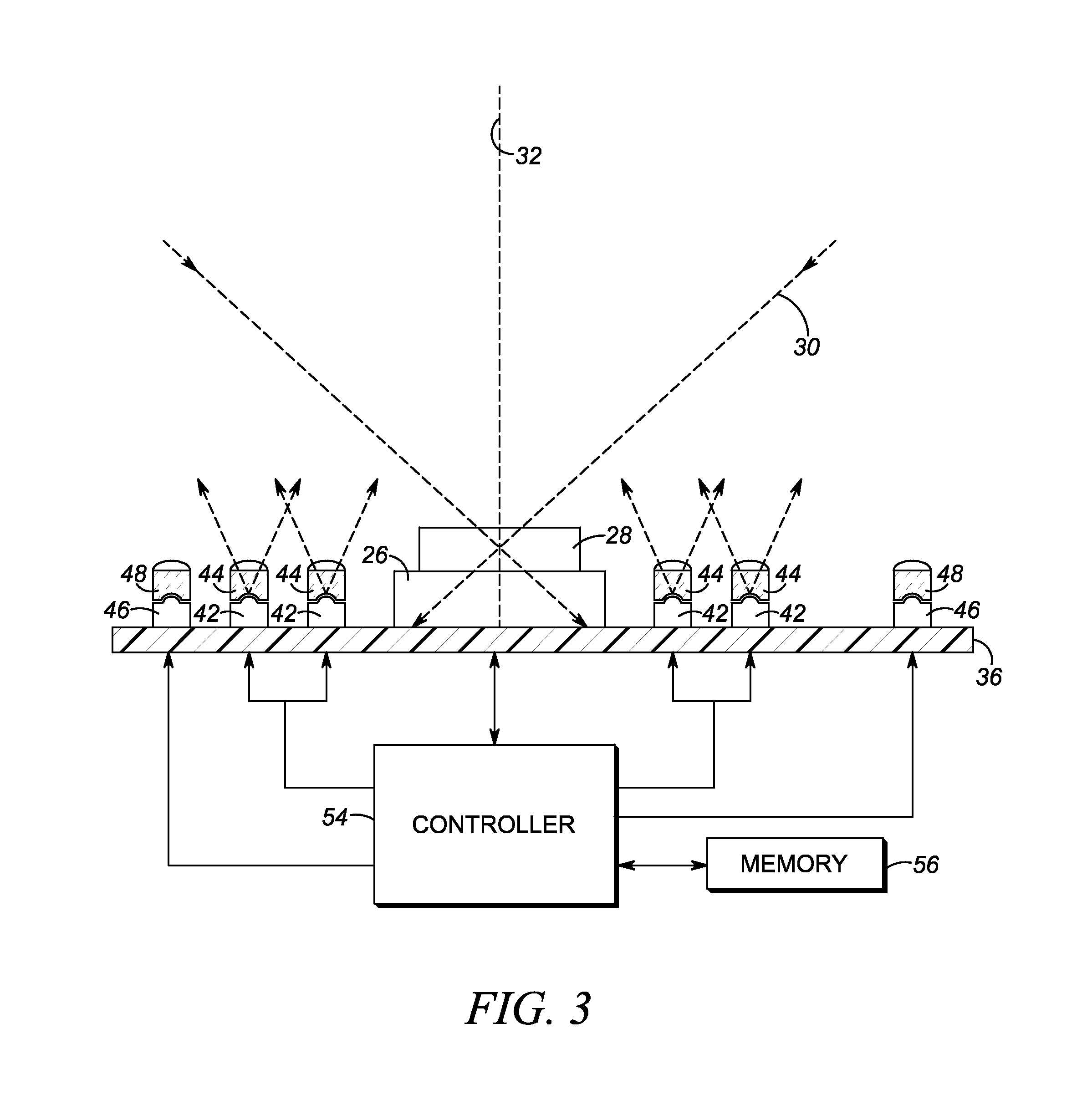
[0019]In accordance with one aspect of the present disclosure, an apparatus for electro-optically reading targets by image capture, includes a housing, a window supported by the housing, an illumination system, an imaging lens system, and an optical element. The illumination system is supported by the housing and is operative for illuminating the targets with illumination light emitted by an illumination light source and directed along an illumination path through the window to the targets. The imaging system includes a solid-state imager supported by the housing and has an array of light sensors looking at an imaging or reading field of view that extends through the window to the targets, and also includes an imaging lens system operative for capturing return illumination light from the targets through the window, and for projecting the captured return illumination light along an imaging path to the array.

[0020]The optical element is located in both the illumination path and the im...


PUM


Abstract

Targets to be electro-optically read by image capture are illuminated with illumination light emitted from an illumination light source and directed along an illumination path through a window to the targets, and return light from the targets is captured through the window and projected along an imaging path to an array of light sensors of an imaging system. An optical element is located in both the illumination path and the imaging path, and has a light-reflecting, non-diffusing portion for directing the captured return light incident on the light-reflecting portion along a folded imaging path to the array, and a light-diffusing portion for diffusing the illumination light incident on the light-diffusing portion along a folded illumination path to scatter and blur an image of the illumination light source, to increase an apparent size of the illumination light source, and to reduce a perceived brightness of the illumination light source.

Description

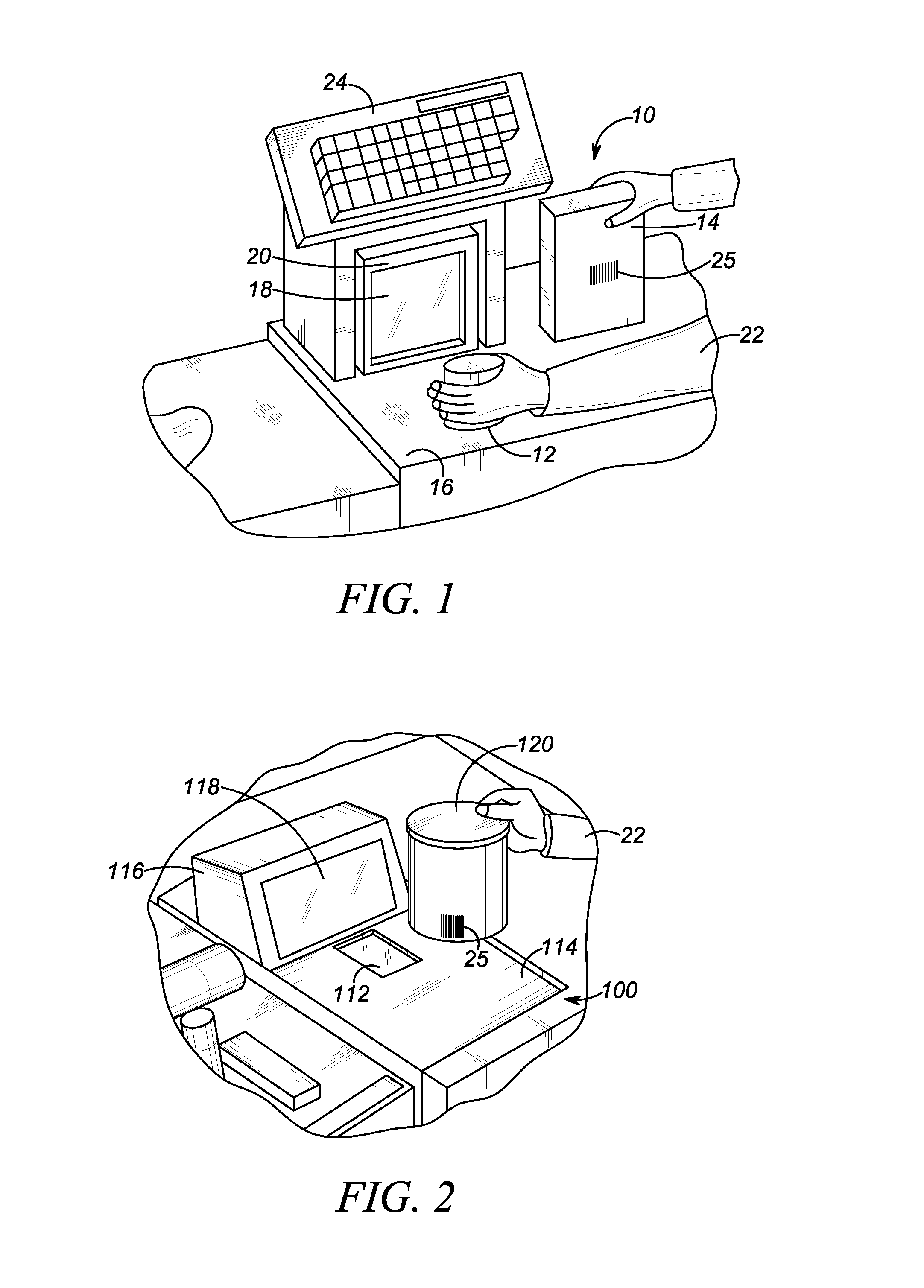
FIELD OF THE DISCLOSURE[0001]The present disclosure relates generally to an apparatus for, and a method of, reading targets by image capture and, more particularly, to illuminating the targets with an illumination light source and, still more particularly, to reducing the perceived brightness of the illumination light source.BACKGROUND[0002]Solid-state imaging readers, that are configured either as vertical slot scanners each having a generally vertically arranged, upright window, or as flat-bed or horizontal slot scanners each having a generally horizontally arranged window, or as bi-optical, dual window scanners each having both generally horizontally and vertically arranged windows, or as stand-mounted, stationary scanners having a presentation window, have been installed as workstations in many venues, such as supermarkets, department stores, and other kinds of retailers, as well as warehouses, and other kinds of industrial settings, for many years, to electro-optically read by ...

Claims


Application Information

Patent Timeline
IPC IPC(8): G06K7/10G06K7/14
CPCG06K7/14G06K7/10831
Inventor VINOGRADOV, IGOR R.LIU, RONGMITELMAN, YULYTRONGONE, ERIC S.
Owner SYMBOL TECH LLC
Learn More