Electric vehicle and electric supply arrangement for the same

a technology for electric vehicles and storage batteries, applied in the field of electric vehicles, can solve the problems of short runnable (travelable) distance based on one full-charging operation, need to take a fairly long time for charging operation, and waste a relatively long time for charging storage batteries. , to achieve the effect of simple and compact structure, high relative magnetic permeability, and large electric power

Inactive Publication Date: 2014-05-15
RUSK INTELLECTUAL RESERVE
View PDF1 Cites 1 Cited by
  • Summary
  • Abstract
  • Description
  • Claims
  • Application Information

AI Technical Summary

Benefits of technology

The present invention is an electric vehicle that can continuously run without needing to stop for battery charging. This is possible because the vehicle has power generating elements located on the inner peripheral surface of the tire, which can generate electrical power from the magnetic field applied from the road surface. The electric power is then supplied to the motor, which drives the wheels to allow the electric vehicle to run. The invention also uses a ground contact portion containing a ferromagnetic material to increase the generation of electric power. Overall, the electric vehicle is efficient, user-friendly, and environmentally-friendly.

Problems solved by technology

However, while the battery-powered electric vehicle requires to charge the storage battery when a charged amount of the storage battery is lowered to a lower limit, there is a problem that it is necessary to take a fairly long time for the charging operation.
Moreover, in the battery-powered electric vehicle, a runnable (travelable) distance based on one full-charging operation is significantly short as compared with an automobile equipped with a gasoline or diesel engine.
Thus, in driving over a long distance by the battery-powered electric vehicle, it is necessary to frequently stop at a battery charging station and spend a fairly long time to charge the storage battery.
Thus, the battery-powered electric vehicle has a problem of causing inconvenience to most users having not a few opportunities of long-distance driving.
As above, despite a strong need for accelerating diffusion the battery-powered electric vehicle, it the above problems cause difficulty in actually promoting the diffusion.

Method used


Image

  • Electric vehicle and electric supply arrangement for the same
  • Electric vehicle and electric supply arrangement for the same
  • Electric vehicle and electric supply arrangement for the same

Examples


first embodiment

[0031]With reference to the accompanying drawings, an electric vehicle and an electric supply arrangement according to a first embodiment of the present invention will now be specifically described.

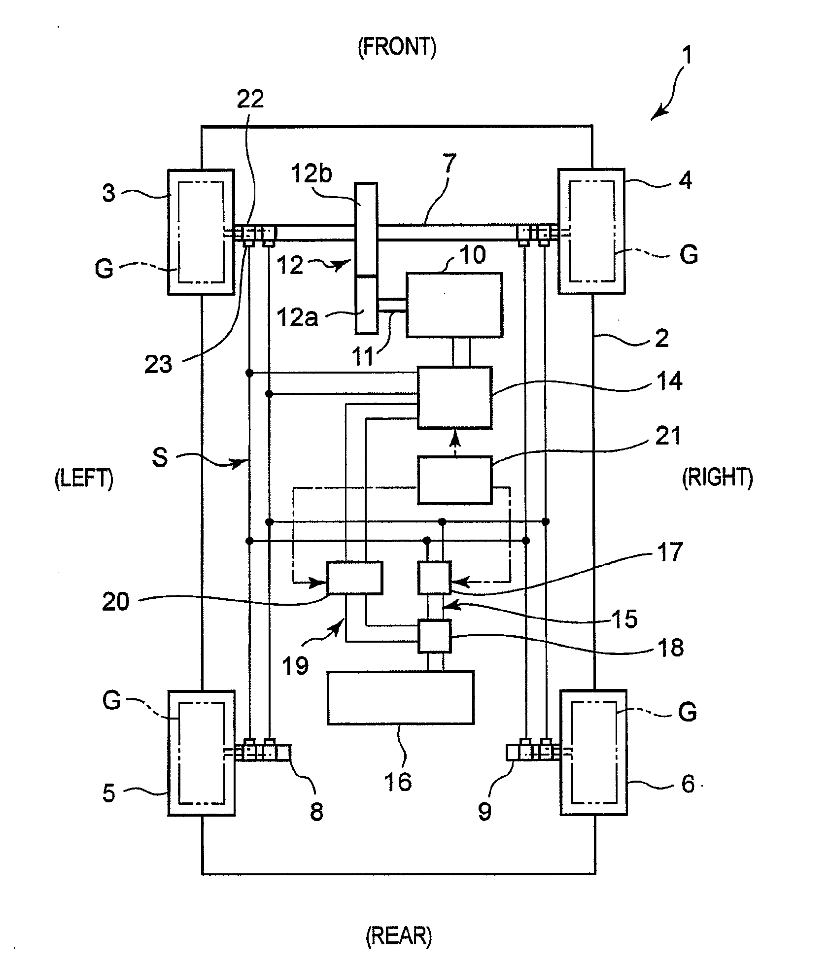
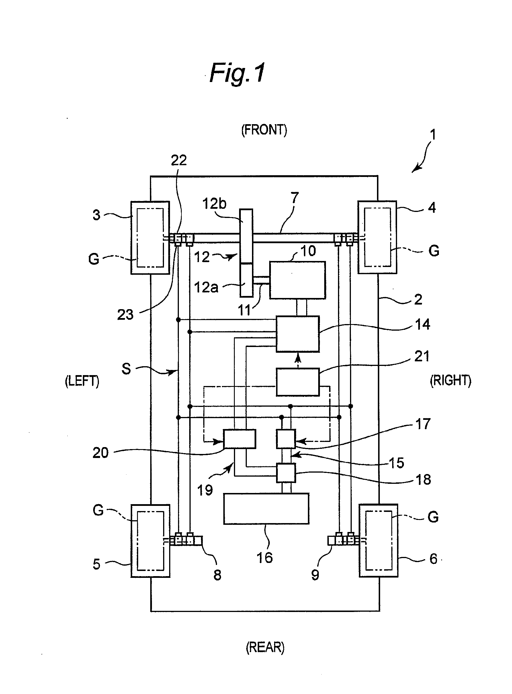
[0032]As shown in FIG. 1, in the electric vehicle 1 according to the first embodiment, a left front wheel 3 is provided on a left side of a front region of a vehicle body 2, and a right front wheel 4 is provided on a right side of the front region of the vehicle body 2. Further, a left rear wheel 5 is provided on a left side of a rear region of the vehicle body 2, and a right rear wheel 6 is provided on a right side of the rear region of the vehicle body 2. In this electric vehicle 1, the left front wheel 3 and the right front wheel 4 are drive wheels, and attached to respective ones of a left end and a right end of a single front wheel drive axle 7 in a concentric relation. Each of the left rear wheel 5 and the right rear wheel 6 is a driven wheel, and attached to respective ones of a le...

second embodiment

[0062]With reference to FIGS. 8 to 11, an electric vehicle and an electric supply arrangement according to a second embodiment of the present invention will now be specifically described. In the second embodiment, a common component to the first embodiment illustrated in FIGS. 1 to 7 is defined by the same reference numeral or code as that in the first embodiment to avoid duplicated description, and its detailed description will be omitted. Therefore, in this specification, the description of the first embodiment is fundamentally applicable to the second embodiment, unless otherwise inconsistent with the following description.

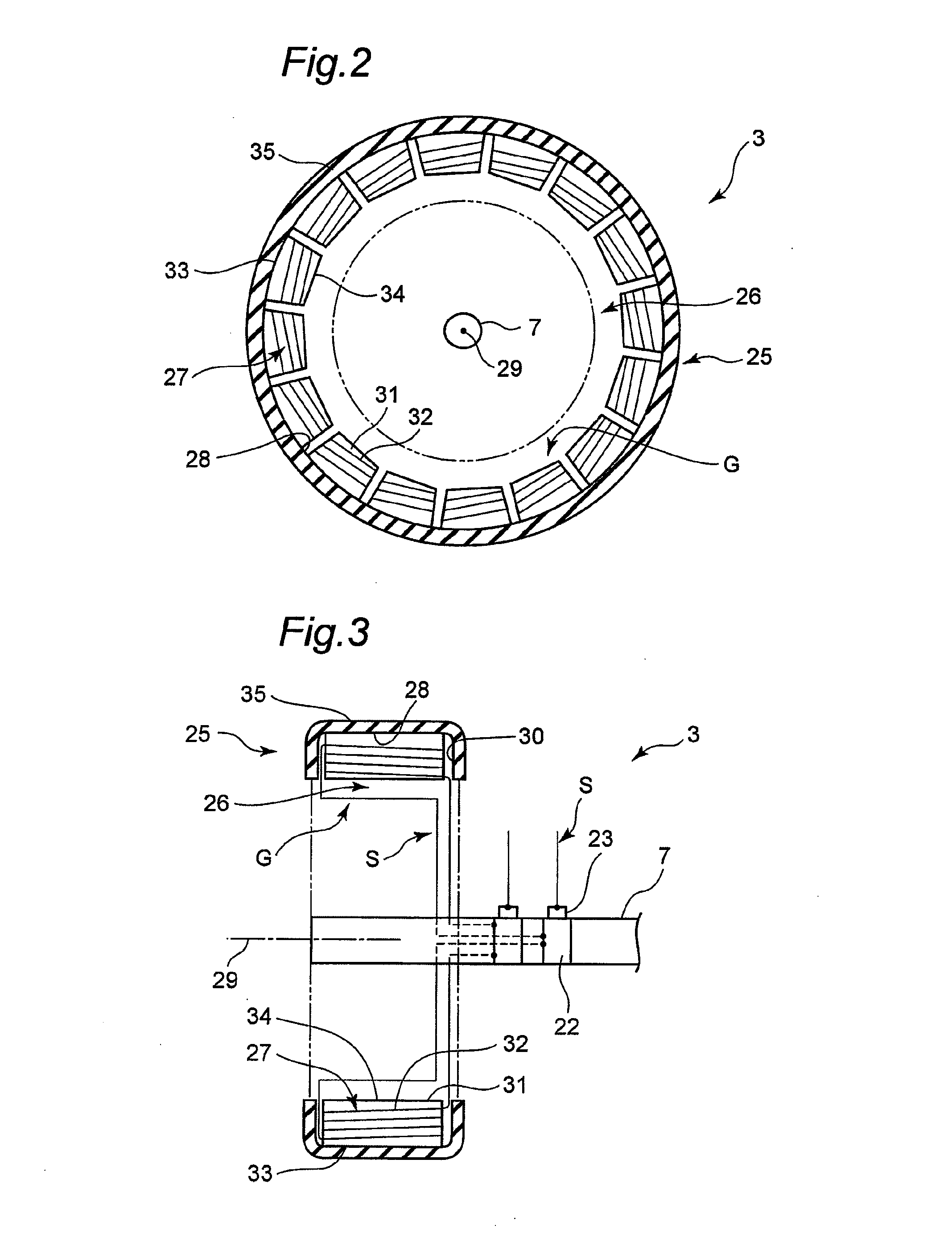
[0063]As mentioned above, in the first embodiment 1, based electric power generated by the power generating units G provided inside the tire 25, through electromagnetic induction, the motor 10 is driven, or the storage battery 16 is charged. In other words, electric power or current is not supply directly from the side of the roads to the electric vehicle 1. Di...


PUM


Abstract

In an electric vehicle, a power unit is installed in an internal space region of a tire of each of front and rear wheels. The unit has a plurality of power elements arranged on an inner peripheral surface of a ground contact portion of the tire. Each of the elements includes a core made of a permalloy, and a power coil wound around the core. When a periodically-changing magnetic field is generated in a region above a road by an electric supply arrangement installed in the road, each of the elements generates electric power. This electric power is supplied to a motor of the vehicle through a power distribution system. The motor drives front wheels. The electric vehicle can continuously run over long distances without charging a battery at a buttery station.

Description

CROSS REFERENCE TO RELATED APPLICATIONS[0001]This divisional application claims the benefit under 35 U.S.C. §120 to U.S. application Ser. No. 12 / 977,253 filed on Dec. 23, 2010. U.S. application Ser. No. 12 / 977,253 is a nonprovisional application claiming the benefit under 35 U.S.C. §119(e) to Provisional Application No. 61 / 290,109 filed on Dec. 24, 2009. The entire contents of the above application are hereby incorporated by reference into the present application.BACKGROUND OF THE INVENTION[0002]The present invention relates to an electric vehicle designed to be supplied with electric power from the outside directly or through electromagnetic induction, during running or stop thereof, and an electric supply arrangement which is installed on / in a road on which the electric vehicle is running or stops, and designed to supply electric power to the electric vehicle directly or through electromagnetic induction.[0003]Heretofore, there has been known a battery-powered electric vehicle whi...

Claims


Application Information

Patent Timeline
Patent Type & Authority Applications(United States)
IPC IPC(8): B60L9/00
CPCB60L9/00Y02T90/14Y02T10/7072B60L53/14B60L53/12H02J7/0068B60L50/53Y02T10/70H02J50/10B60L50/50Y02T90/12
Inventor UENO, RYUJINAKATA, MISAKO
Owner RUSK INTELLECTUAL RESERVE
Why Eureka
Try Eureka