Condensate discharge device for compressed gas systems
- Summary
- Abstract
- Description
- Claims
- Application Information
AI Technical Summary
Benefits of technology
Problems solved by technology
Method used
Image
Examples
Embodiment Construction
[0031]In the various figures, identical parts are always provided with the same reference numbers, so that as a rule they are described only once.
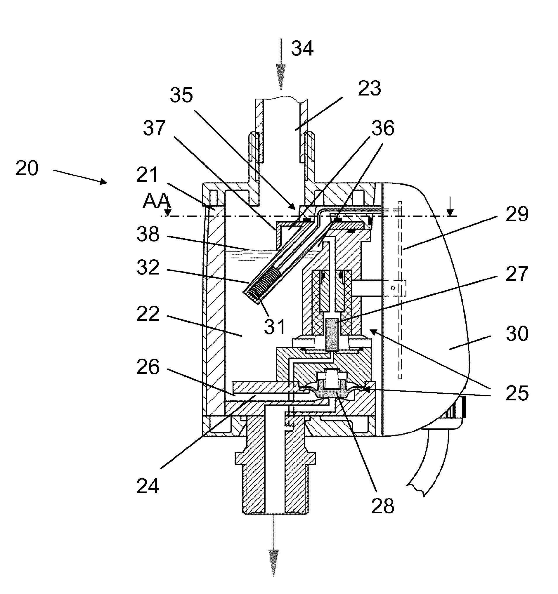
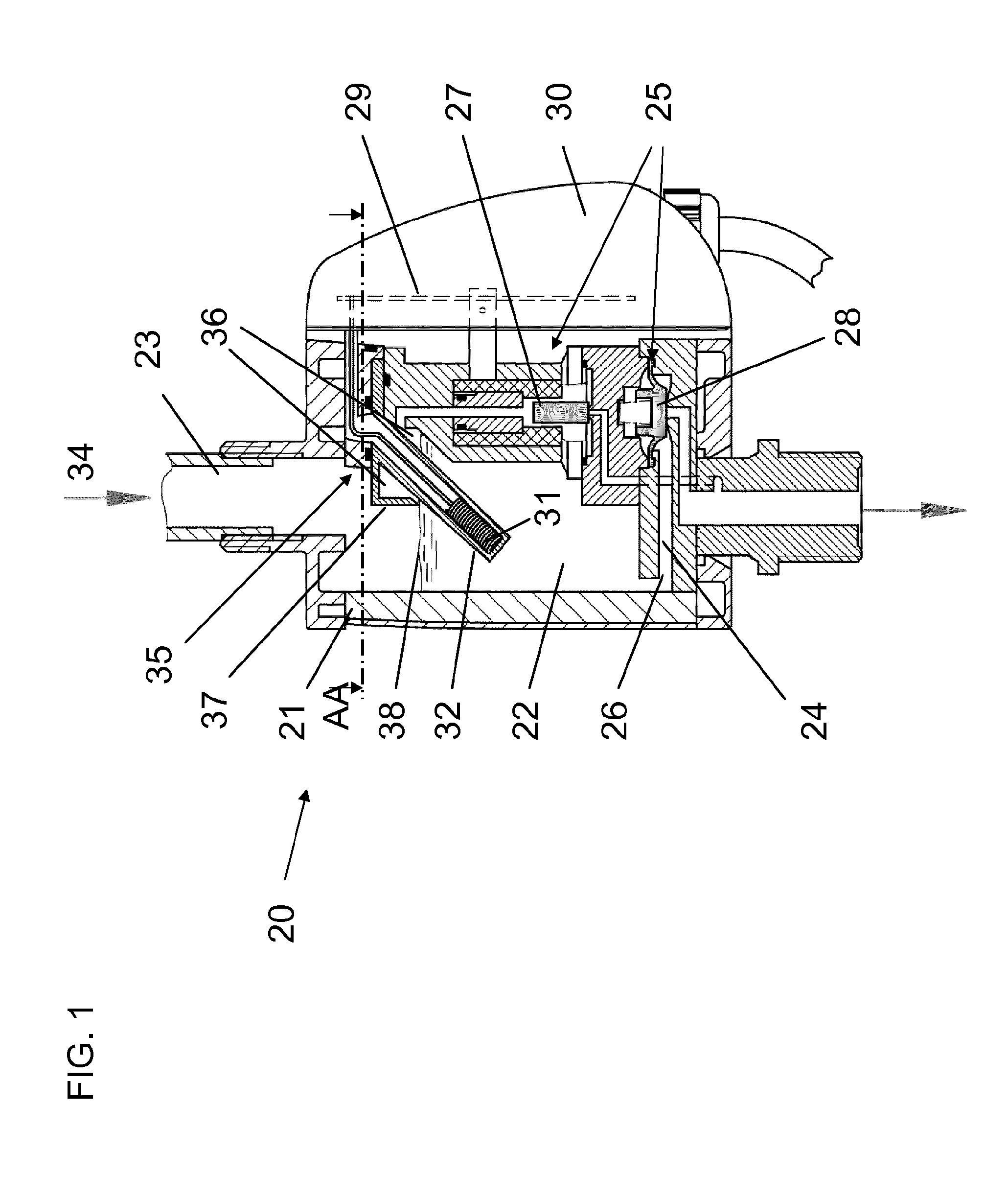
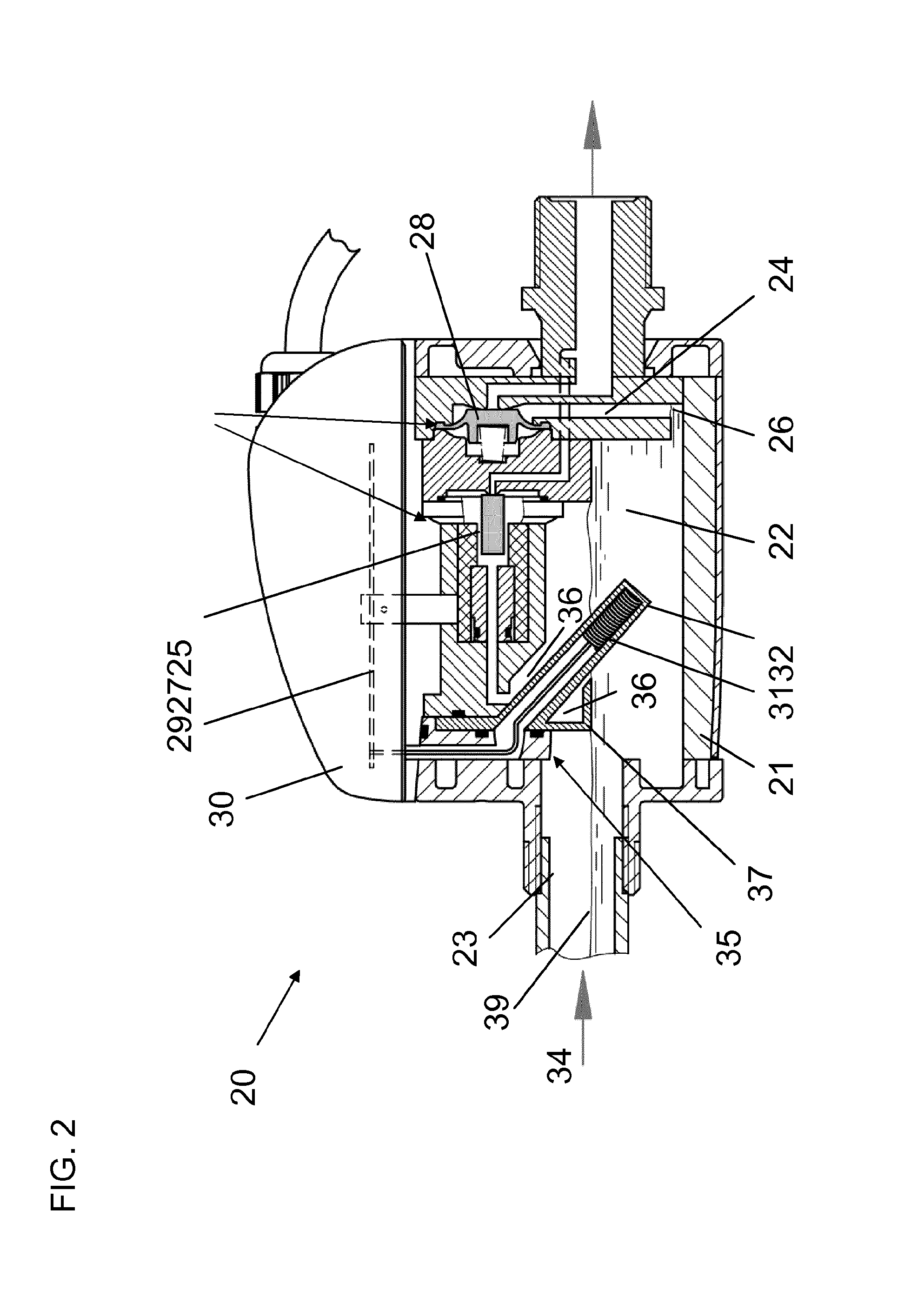
[0032]FIG. 1 shows a cross-sectional side view of an example of embodiment of a condensate discharge device 20 according to the invention for compressed gas systems, in particular for compressed air systems, in a first, vertical mounting position. Condensate discharge device 20 comprises a housing 21, which comprises a condensate collecting chamber 22. Condensate collecting chamber 22 can be connected via a condensate feed 23 to the compressed gas system not represented in detail in FIG. 1. Condensate from the compressed gas system can flow via condensate feed 23 to condensate collecting chamber 22. The condensate passes out of condensate collecting chamber 22 again via a condensate drain 24. Condensate drain 24 can be closed by means of a valve assembly 25. As can be seen in FIG. 1, a mouth 26 of condensate drain 24 is disposed in a left-...
PUM
 Abstract
Description
Claims
Application Information
 - R&D Engineer
- R&D Manager
- IP Professional
- Industry Leading Data Capabilities
- Powerful AI technology
- Patent DNA Extraction
Browse by: Latest US Patents, China's latest patents, Technical Efficacy Thesaurus, Application Domain, Technology Topic, Popular Technical Reports.
© 2024 PatSnap. All rights reserved.Legal|Privacy policy|Modern Slavery Act Transparency Statement|Sitemap|About US| Contact US: help@patsnap.com


