seat
a seat and seat technology, applied in the field of seats, can solve the problems of seated person's hip undesirably sinking downwardly, seated person's back undesirably sinking rearwardly, etc., and achieve the effect of preventing the disengagement of the hook member
- Summary
- Abstract
- Description
- Claims
- Application Information
AI Technical Summary
Benefits of technology
Problems solved by technology
Method used
Image

Examples
first embodiment
[0016]With reference to FIGS. 1, 2A and 2B, the present invention will now be described.
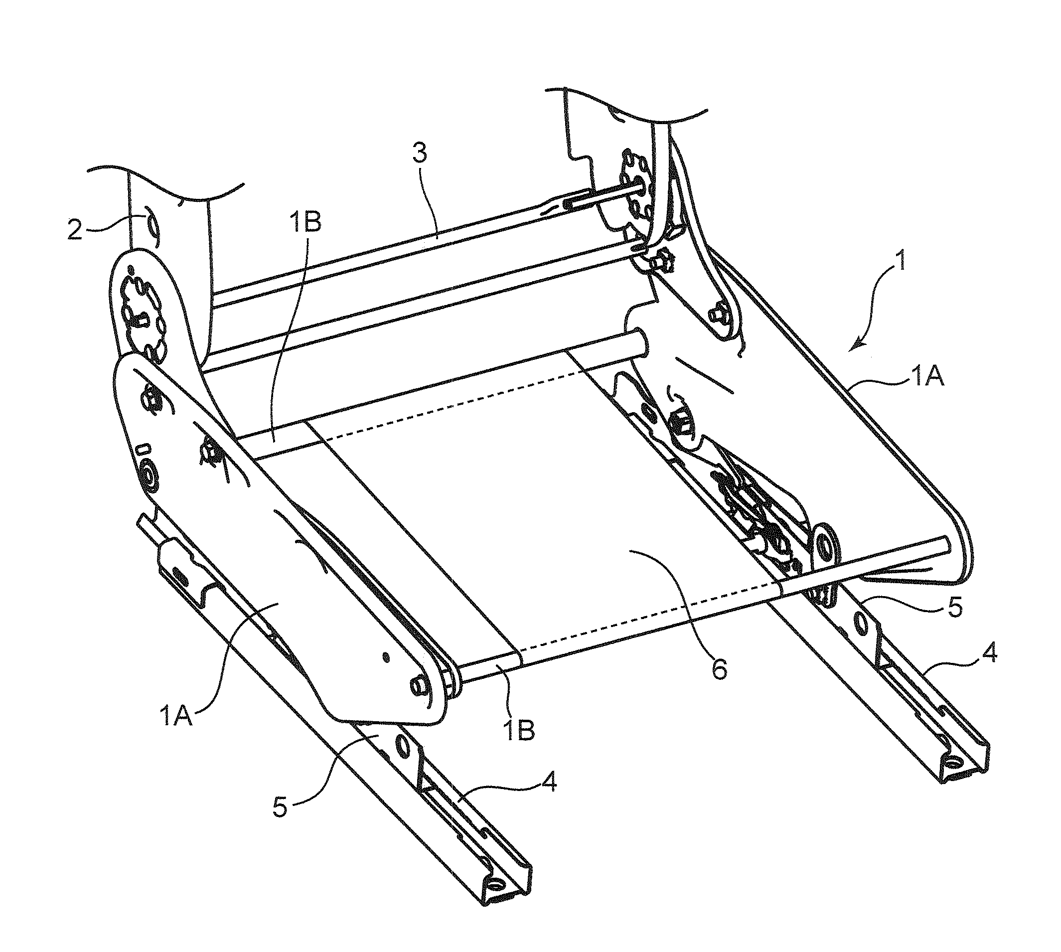
[0017]As illustrated in FIG. 1, an automobile seat according to the first embodiment comprises therein a cushion frame 1 constituting a framework for a seat cushion, and a back frame 2 constituting a framework for a seat back. The back frame 2 is supported tiltably in a front-rear direction of an automobile body with respect to the cushion frame 1 via a reclining mechanism including a reclining shaft 3. In the first embodiment, an anti-expansion mechanism in the present invention is applied to a lock section between the cushion frame 1 and an aftermentioned first hook member 7, although details thereof will become apparent from the following description. Thus, in the first embodiment, the cushion frame 1 is equivalent to “seat frame” set forth in the appended claims.
[0018]The cushion frame 1 comprises a pair of right and left first frame members 1A, 1A, and a pair of front and rear second frame m...
second embodiment
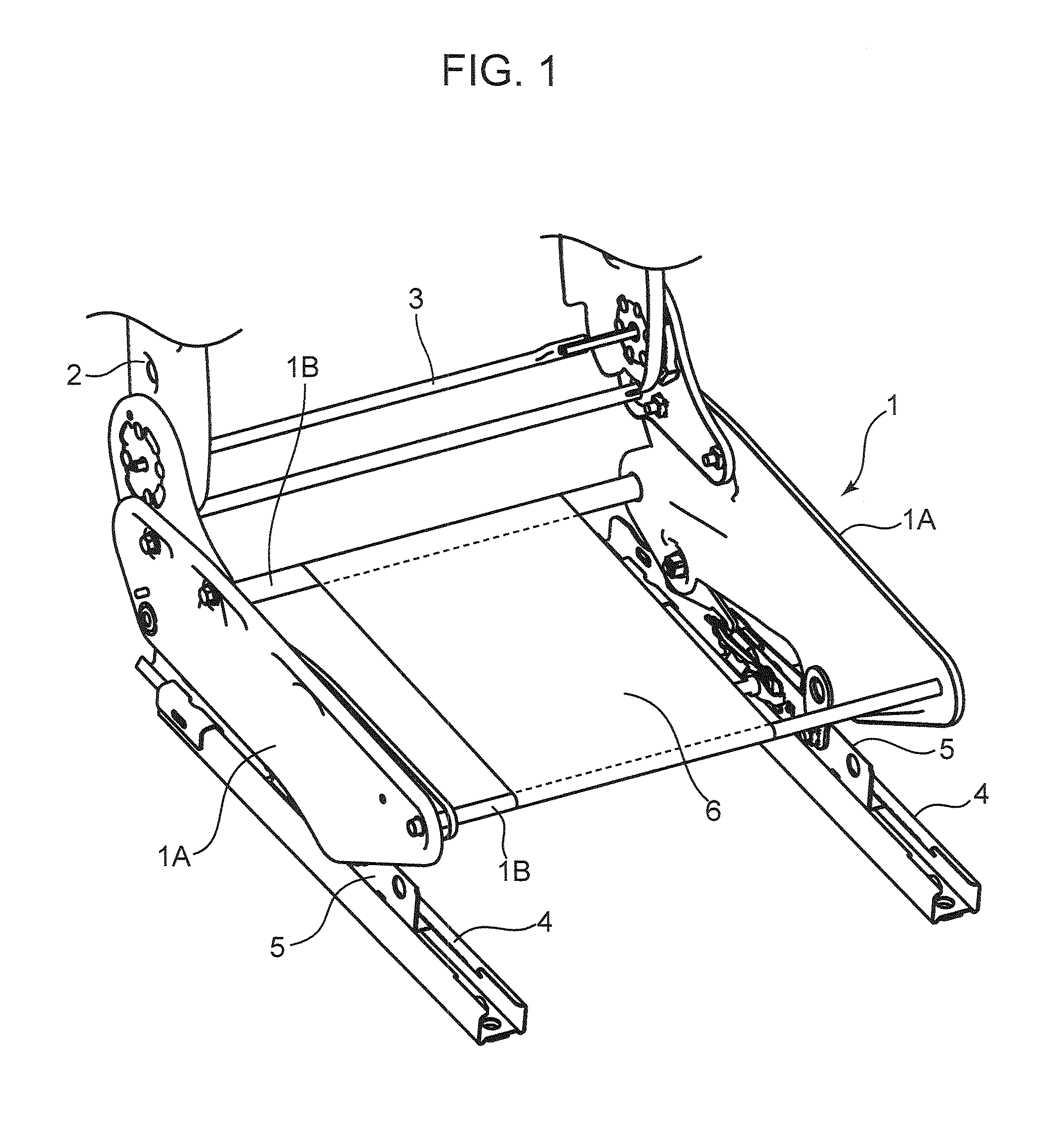
[0037]As above, in the second embodiment, when the planar elastic body 6 is pressed and stretched inwardly by receiving a relatively large load, for example, based on a body weight of a seated person, a circumferential tension is applied to a region of the planar elastic body 6 being wound around the locking portion 7a of the first hook member 7. Thus, based on this circumferential tension, a clamping force causing the locking portion 7a to come into close contact with the outer peripheral surface of the second frame member 1B is applied to the locking portion 7a from the planar elastic body 6, particularly, from a region of the planar elastic body 6 indicated by the code Y in FIG. 3A. Such a clamping force fulfills a function of avoiding the situation where the synthetic resin first hook member 7 is flexurally deformed to expand the mouth X of the locking portion 7a, so that it becomes possible to effectively prevent disengagement of the first hook member 7 from the second frame me...
third embodiment
[0040]Specifically, the first hook member 17 in the third embodiment has: a base portion 17b; a locking portion 17a; an extension portion 17c extending from a distal end of the locking portion 17a inwardly (in FIG. 4A, leftwardly) with respect to the cushion frame 1 and obliquely upwardly; and a pawl portion 17d provided at a distal end of the extension portion 17c and lockable to a base end 17b1 of the base portion 17b.
[0041]In an operation of locking the above first hook member 17 to the second frame member 1B, first of all, as illustrated in FIG. 4B, the first hook member 17 is elastically deformed to expand a gap between the base end 17d1 and the pawl portion 17d, and, in this state, the second frame member 1B is inserted into an inside of the first hook member 17. Then, as illustrated in FIG. 4A, the pawl portion 17d of the first hook member 17 is locked to the base end 17b1.
[0042]The front end portion 6a of the planar elastic body 6 is wound around not only an outer periphera...
PUM
 Abstract
Description
Claims
Application Information
 - R&D
- Intellectual Property
- Life Sciences
- Materials
- Tech Scout
- Unparalleled Data Quality
- Higher Quality Content
- 60% Fewer Hallucinations
Browse by: Latest US Patents, China's latest patents, Technical Efficacy Thesaurus, Application Domain, Technology Topic, Popular Technical Reports.
© 2025 PatSnap. All rights reserved.Legal|Privacy policy|Modern Slavery Act Transparency Statement|Sitemap|About US| Contact US: help@patsnap.com