Radiation member
a technology of radiation member and member, which is applied in the field of radiation member, can solve the problems of difficult precipitation of metal particles, limited use of metal, and complicated manufacturing process
- Summary
- Abstract
- Description
- Claims
- Application Information
AI Technical Summary
Benefits of technology
Problems solved by technology
Method used
Image


Examples
first embodiment
Structure of Radiation Member of First Embodiment
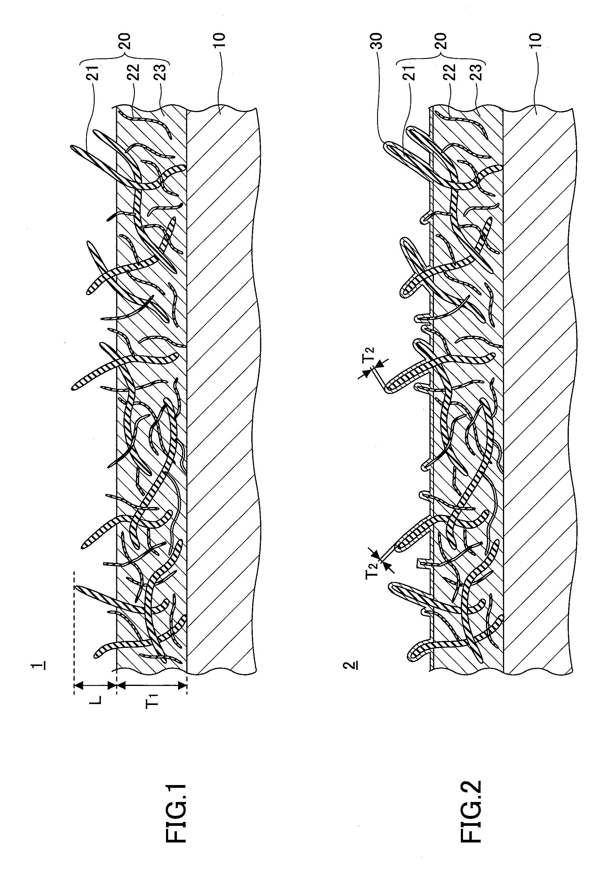
[0019]First, a structure of a radiation member of a first embodiment is explained. FIG. 1 is a partial schematic cross-sectional view illustrating an example of a radiation member 1 of the first embodiment. The radiation member 1 includes a base material 10 and a composite plating layer 20.
[0020]The base material 10 is a portion on which the composite plating layer 20 is formed. The base material 10 may be made of metal having a good thermal conductivity. Specifically, for the base material 10, for example, copper (Cu), aluminium (Al), an alloy of these, or the like may be used. Alternatively, the base material 10 may be made of resin, silicon or the like.
[0021]The composite plating layer 20, formed on the base material 10, includes a metal layer 23 and first carbon nanotubes 21 and second carbon nanotubes 22 (hereinafter, referred to as first CNT 21 and second CNT 22, respectively) dispersed in the metal layer 23. The thickness T1 of...
second embodiment
[0046]In a second embodiment, an example is explained in which a surface plating layer is formed on the composite plating layer via a catalyst layer.
(Structure of Radiation Member of Second Embodiment)
[0047]First, a structure of a radiation member of the second embodiment is explained. FIG. 2 is a partial schematic cross-sectional view illustrating an example of a radiation member 2 of the second embodiment. The radiation member 2 is different from the radiation member 1 (see FIG. 1) of the first embodiment at a point that a surface plating layer 30 is formed on the composite plating layer 20 via a catalyst layer (not illustrated in the drawings).
[0048]The catalyst layer (not illustrated in the drawings) is formed to cover the surface of the composite plating layer 20. Specifically, the catalyst layer is formed to cover the surfaces of the protruding portions of the first CNT 21 and the second CNT 22 and the surface of the metal layer 23. The catalyst layer is made of a catalytic ag...
example
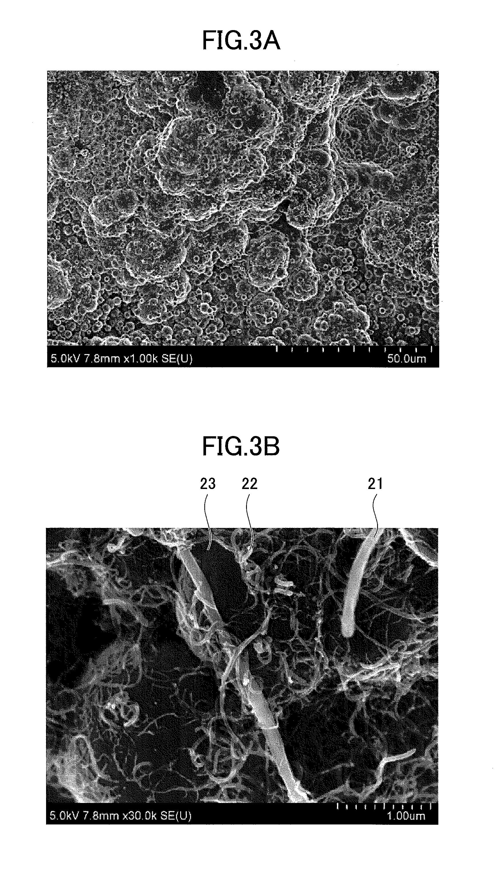
[0064]In this example, the radiation member 1 was manufactured in accordance with the method explained in the first embodiment. Specifically, a copper plate was used as the base material 10, and the composite plating layer 20 having a thickness of 5 μm was formed thereon by using Ni—P plating solution as the electroless plating solution. The method is explained in the following in detail.
[0065]Composition of Ni—P plating solution is as illustrated in Table 1. The diameters, lengths and densities of the first CNT 21 and the second CNT 22 are as illustrated in Table 2. As illustrated in Table 1, 1.7×10⁻³ mol / l of trimethyl-cetyl-ammonium chloride (TMSAC) was added to Ni—P plating solution as a surface-active agent (a dispersant).
TABLE 1CONCENTRATION MCOMPOSITION(mol / l)NiSO4•6H2O0.1NaH2PO2•H2O0.2C6H5Na3O70.2(NH4)2SO40.5TMSAC1.7 × 10−3
TABLE 2DIAMETERLENGTHCONCENTRATION(nm)(μm)(g / l)FIRST CNT100~15010~20—SECOND CNT0.8~20 1~10—FIRST CNT AND——2SECOND CNT
[0066]An object to be plated (base m...
PUM
 Abstract
Description
Claims
Application Information
 - R&D
- Intellectual Property
- Life Sciences
- Materials
- Tech Scout
- Unparalleled Data Quality
- Higher Quality Content
- 60% Fewer Hallucinations
Browse by: Latest US Patents, China's latest patents, Technical Efficacy Thesaurus, Application Domain, Technology Topic, Popular Technical Reports.
© 2025 PatSnap. All rights reserved.Legal|Privacy policy|Modern Slavery Act Transparency Statement|Sitemap|About US| Contact US: help@patsnap.com