Z-folding three-dimensional-structure former

Inactive Publication Date: 2014-05-01
EASTMAN KODAK CO
View PDF26 Cites 6 Cited by
  • Summary
  • Abstract
  • Description
  • Claims
  • Application Information

AI Technical Summary

Benefits of technology

The patent describes using toner as an adhesive to create a three-dimensional structure. This toner adhesive is lighter than other adhesives, and can be used in smaller amounts. The stiffness of the structure can be controlled by selecting the pattern of the toner. Unlike other methods, the toner is used to hold the different parts of the structure together, creating tall and strong structures with low mass. The toner is also weather-resistant and can be used on wet paper. This invention improves the strength and stiffness of the structure while reducing its weight and mass.

Problems solved by technology

This form of corrugation is more expensive than conventional corrugation because of the increased use of polymeric materials and further suffers from weaknesses at the joints in that the joints are typically thin polymeric supports which are subject to lateral collapse when subjected to shear forces.
However, it is difficult for many high quality printing systems to print on thick stiff corrugated substrates, particularly using high volume presses that are intended for use with thinner more flexible roll fed web media.
However, these schemes are very limited in the thickness, and therefore in the mechanical strength, they can provide.
However, those properties cannot readily be adjusted depending on the type of product to be packaged.
This restricts the box designer's freedom to adjust the mechanical characteristics of the box based on its intended use.
This relative strength configuration cannot be provided by conventional corrugated materials.
Extra space in each box is filled with packing materials that add additional weight and cost.
In addition, maintaining an inventory of the packaging materials and boxes cost money and takes up space.
This requires that any desired product marketing, promotional, or trade dress or authentication indicia be printed on the box during the shipping process when it can be difficult to provide the high quality printing that is required to form a high quality image.
Conventional corrugated materials have structural limitations.
Such adhesives are water-soluble rendering these vulnerable to catastrophic failure in the event that such boxes are exposed to water.
However, these adhesives change volume when they cool, producing internal stresses that can weaken the structural integrity of the corrugated cardboard material, make the corrugated material less planar, or create sinusoidal variations in a surface of the corrugated that make the surface less attractive as a surface on which images are to be printed and that make it more difficult to print on such surfaces.
Composite materials can be formed in curved shapes and other shapes difficult to make with other similarly-strong materials.
However, the manufacturing of composite materials, especially in curved shapes, is generally energy intensive, time consuming, and expensive.
Each composite shape to be produced requires separate molds, increasing the cost of production tooling.

Method used


Image

  • Z-folding three-dimensional-structure former
  • Z-folding three-dimensional-structure former
  • Z-folding three-dimensional-structure former

Examples


Embodiment Construction

[0053]As used herein, the terms “receiver,”“receivers,”“medium,”“media,”“recording medium,” and “recording media” are used interchangeably. “Receivers” (or any equivalent term) include objects extending (or that can be arranged to extend) significantly farther in two directions than in a third direction of three mutually-orthogonal directions. Most receivers have significant length and width, e.g., 8″×11″, but very little thickness, e.g., 4 mil (˜0.1 mm). “Sheet” and “web” receivers are used interchangeably except when discussing aspects that are particularly adapted to use one of those styles of receiver. “Adhere” is used herein both intransitively (toner adheres to paper) and transitively (toner adheres two sheets to each other, i.e., the adhesive forces between a toner mass and each of two sheets holds those two sheets together).

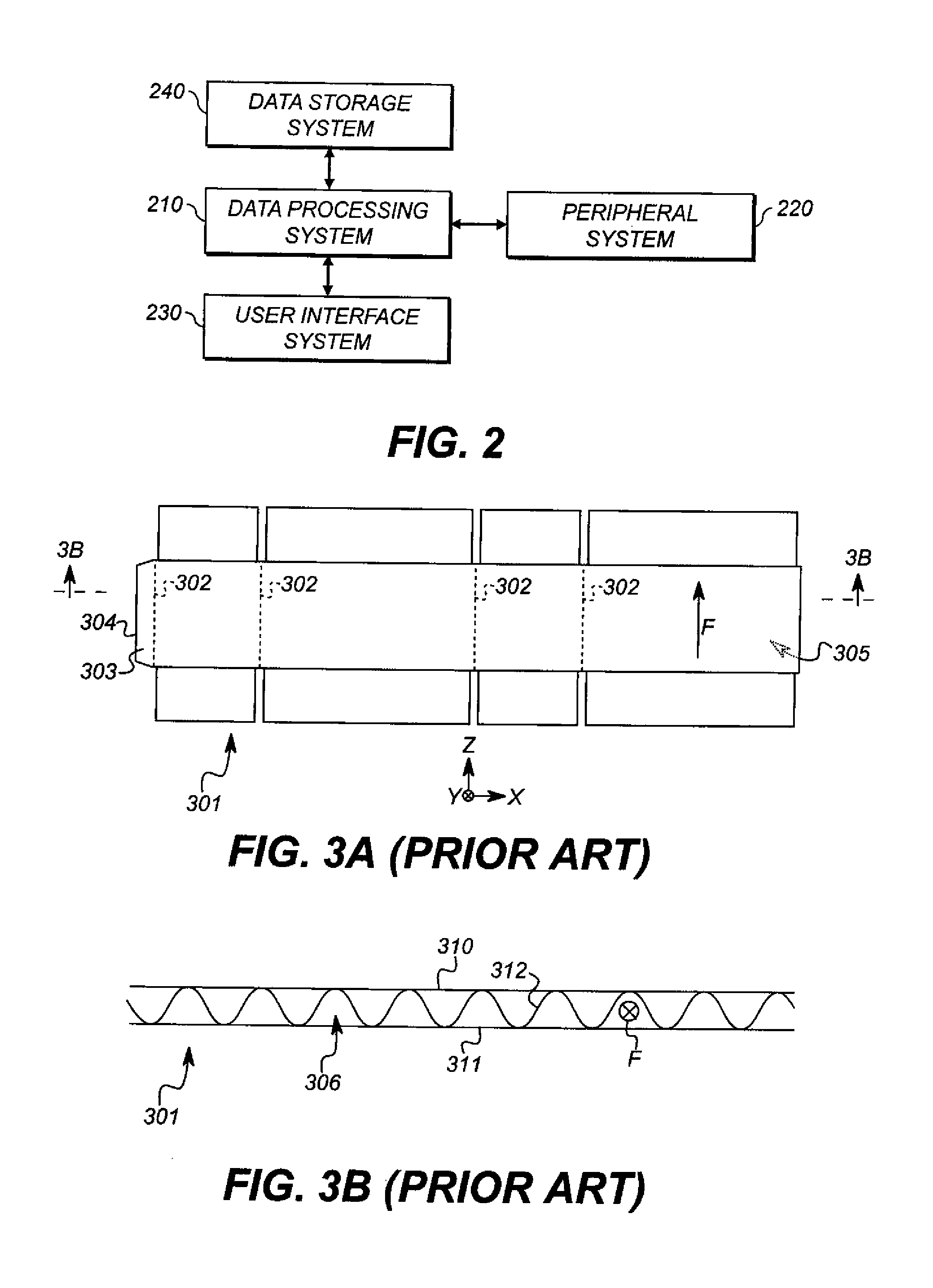
[0054]Referring back to FIG. 3B, the direction of extension F of flutes 306 is the direction in which a ray extended in direction F will not cross fluted...


PUM


Abstract

A device for producing a three-dimensional structure from a receiver includes a deposition unit that deposits toner on two surfaces of the receiver. That unit is controlled by a controller to produce a toner pattern on the first surface of the receiver. A softening device softens the toner. An automatic z-fold system makes a z-folded stack of separate portions of a length of the receiver, each portion being joined to at least one other portion in the z-folded stack by at least one of the z-folds. The z-fold system brings two separate portions of the same surface of the receiver into contact, at least one portion carrying softened toner.

Description

CROSS-REFERENCE TO RELATED APPLICATIONS[0001]This application is co-filed with and has related subject matter to U.S. patent application Ser. No. ______, filed herewith, titled “FORMING THREE-DIMENSIONAL STRUCTURE FROM RECEIVER;” U.S. patent application Ser. No. ______, filed herewith, titled “INCREMENTALLY FORMING THREE-DIMENSIONAL STRUCTURE FROM RECEIVER;” and U.S. patent application Ser. No. ______, filed herewith, titled “THREE-DIMENSIONAL-STRUCTURE FORMER;” each of which is incorporated herein by reference in its entirety.FIELD OF THE INVENTION[0002]This invention pertains to the field of printed manufacturing and more particularly to printing three-dimensional structures.BACKGROUND OF THE INVENTION[0003]Corrugated cardboard is widely used to package goods for transit. Such corrugated cardboard, typically comprises an outer sheet of liner sheet (or “linerboard”) that is glued to a fluted sheet and a second outer sheet of liner is glued to the fluted sheet opposite the first out...

Claims


Application Information

Patent Timeline
IPC IPC(8): B31F1/20B31F1/00
CPCB31F1/20B31F1/00G03G15/224G03G15/231G03G15/6582
Inventor SCHINDLER, II, ROLAND R.RIMAI, DONALD SAUL
Owner EASTMAN KODAK CO
Why Eureka
Try Eureka