Dispensing assembly and method using snap engagement of a mixer and a cartridge

a technology of dispensing assembly and cartridge, which is applied in the direction of dispensing apparatus, packaging, coating, etc., can solve the problems of limiting the structural strength and rigidity possible, and affecting the dispensing effect of the dispensing devi

Active Publication Date: 2014-05-01
NORDSON CORP
View PDF7 Cites 20 Cited by
  • Summary
  • Abstract
  • Description
  • Claims
  • Application Information

AI Technical Summary

Benefits of technology

[0013]In yet another aspect of the invention, the dispensing assembly further includes a sealing cap configured to engage the cartridge to close the outlet socket when the mixer is disengaged from the cartridge. The sealing cap includes first and second locking latches configured to snap into engagement with the proximal wall and first and second squeeze handles coupled to the first and second locking latches. The first and second squeeze handles are configured to be depressed toward one another to snap the first and second locking latches out of engagement with the proximal wall. The sealing cap also includes a blocking member coupled to the first and second squeeze handles and located between the first and second squeeze handles. The blocking member prevents unintentional depression of the first and second squeeze handles toward one another until the blocking member is removed from the sealing cap.

Problems solved by technology

The rotary locking and unlocking movement required to use this type of bayonet connection may lead to the transport and cross contamination of one fluid from a first outlet of the cartridge to another fluid in the second outlet of the cartridge.
If the fluids being mixed together from the cartridge react with one another, as is typical in these dispensing systems, then this cross contamination may eventually carry this reaction into the fluid chamber of the cartridge itself, leading to blockage of one or both of the outlets.
Furthermore, the bayonet-style tabs must generally be formed with a very small size, which limits the structural strength and rigidity possible to counteract ever increasing backpressures formed when using smaller diameter mixers.
These threaded components are difficult to manufacture reliably with the tight tolerances required to ensure a viable seal between the mixer and the cartridge.
Additionally, these threaded components generally require multiple rotations of the threaded ring to engage the mixer with the cartridge.
As a result, the installation and removal process for each mixer is an inefficient and time-consuming process.

Method used


Image

  • Dispensing assembly and method using snap engagement of a mixer and a cartridge
  • Dispensing assembly and method using snap engagement of a mixer and a cartridge
  • Dispensing assembly and method using snap engagement of a mixer and a cartridge

Examples


Embodiment Construction

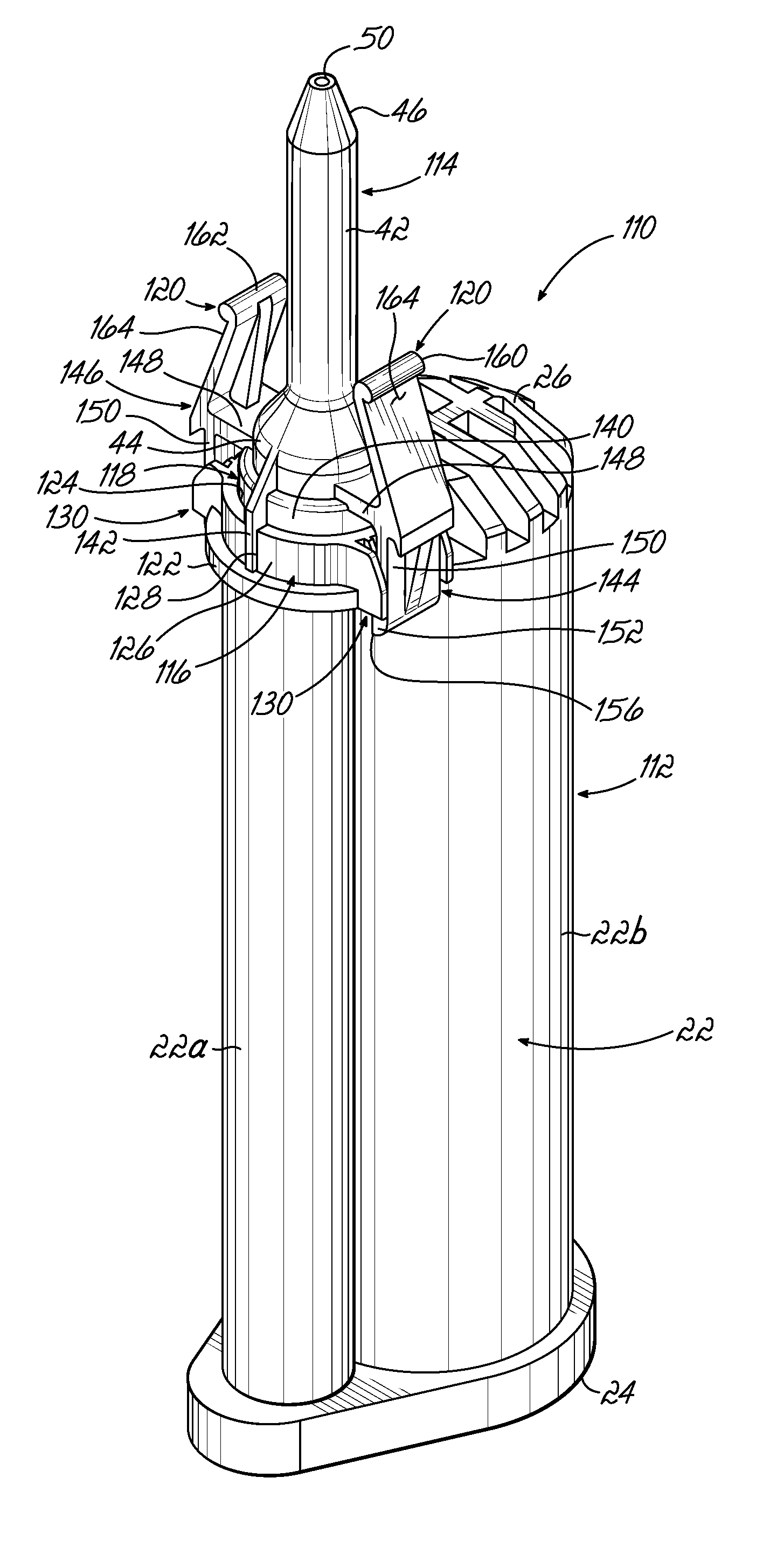
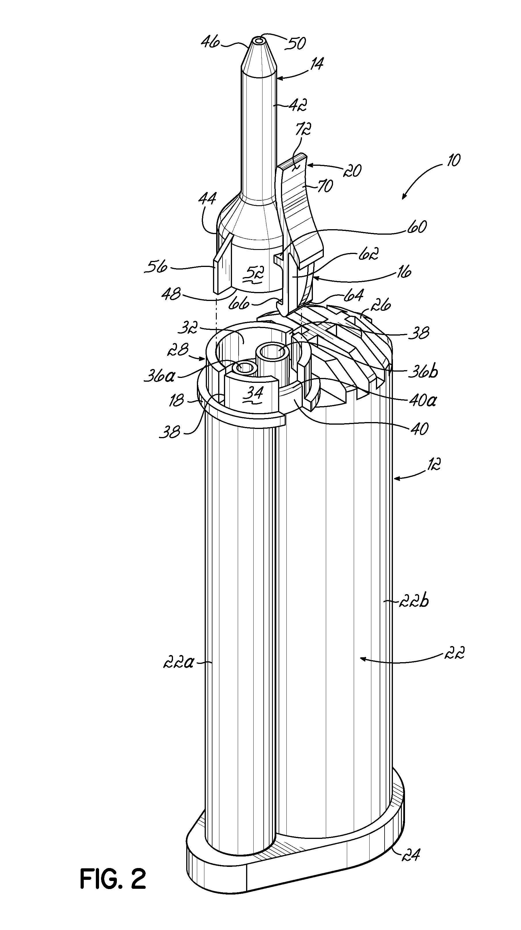
[0052]Referring to FIGS. 1-6B, a first embodiment of a dispensing assembly 10 in accordance with the principles of the current invention is shown. Generally speaking, the dispensing assembly 10 includes a cartridge 12 for containing a fluid to be dispensed and a mixer 14 in the form of a static mixer 14 configured to mix and dispense the fluid in the cartridge 12. As a result of the lengths of each of these elements 12, 14 and the desire to use different mixers 14 with the same cartridge 12 (and vice versa), the cartridge 12 and the mixer 14 are manufactured and shipped separately and then must be assembled before a dispensing operation. Advantageously, the mixer 14 includes a first locking latch 16 operable to snap into and out of engagement with a corresponding flange or wall on the cartridge 12. In the first embodiment of FIGS. 1-6, for example, the first locking latch 16 extends from the mixer 14 and is configured to snap into and out of engagement with a proximal wall 18 define...


PUM


Abstract

A dispensing assembly includes a cartridge for containing a fluid and a mixer for mixing and dispensing the fluid. The cartridge includes a locking flange or wall and the mixer includes a locking latch configured to snap into and out of engagement with the locking flange. To this end, the mixer and the cartridge are coupled and uncoupled by a snap-on and snap-off engagement that does not require relative rotation of the mixer and the cartridge. The locking latch also includes a latch release mechanism such as a squeeze handle, a peel handle, or a locking ring for forcing the locking latch into and out of engagement with the locking flange. As a result, the connection of the mixer and the cartridge is a quick and easy process and cross contamination of fluids in multiple fluid cartridges is avoided.

Description

FIELD OF THE INVENTION[0001]The present invention generally relates to a dispensing assembly and method and, more particularly, to components of a mixer and a cartridge configured to retain these elements in engagement together during dispensing.BACKGROUND[0002]In the dispensing field, it is common to manufacture and ship cartridges holding the fluid to be dispensed and static mixers separately. There are a number of reasons for this separate shipping, including, but not limited to, the excessive length of some mixer / cartridge combinations and the potential use of a plurality of different mixers with a cartridge. Consequently, the mixers and cartridges need to be provided with corresponding connection members that may sealingly couple the mixer to an outlet of the cartridge and enable removal of the mixer from the cartridge after use. Moreover, many known cartridges include separated outlets for delivering two or more fluids into the mixer to be mixed before dispensing. As a result,...

Claims


Application Information

Patent Timeline
Patent Type & Authority Applications(United States)
IPC IPC(8): B65D25/48
CPCA61M5/3294A61M5/348B05C17/00506B05C17/00553
Inventor PAPPALARDO, MATTHEW E.
Owner NORDSON CORP
Why Eureka
Try Eureka