
Projector and method for controlling projector

a projector and projector technology, applied in the field of projectors and a control method of projectors, can solve the problems of reducing the reliability of lamps, reducing the performance of optical parts that form liquid crystal panels, and increasing the temperature of enclosures, so as to achieve the effect of lowering the frequency of switching between the activation and deactivation of the first fan

Active Publication Date: 2014-04-24
SEIKO EPSON CORP
View PDF9 Cites 7 Cited by
  • Summary
  • Abstract
  • Description
  • Claims
  • Application Information

AI Technical Summary

Benefits of technology

The technical effect of this patent is to provide a projector that can have both reliable components and perform well in a variety of optical parts.

Problems solved by technology

The reason for this is that an increase in temperature in the enclosure due to use of a high-intensity lamp lowers the performance of optical parts that form a liquid crystal panel, a polarization conversion system, a color separation / light combining system, and other optical systems.
In this case, vapor in the lamp condenses, resulting in a problem of a decrease in reliability of the lamp.
The reason for this is that completely stopping the cooling fan is not preferable because the temperatures of a variety of optical parts increase and performance and reliability thereof may not be ensured.
The designer is therefore not free to set the specifications of the cooling fan running at a low rotational speed.

Method used


Image

  • Projector and method for controlling projector
  • Projector and method for controlling projector
  • Projector and method for controlling projector

Examples


first embodiment

[0034]A first embodiment of the invention will be described below with reference to FIGS. 1 to 4A and 4B.

[0035]A projector according to the present embodiment is an example of what is called a three-panel liquid crystal projector including three sets of liquid crystal light valves.

[0036]In the following drawings, each component is not drawn to scale in some cases for ease of illustration thereof.

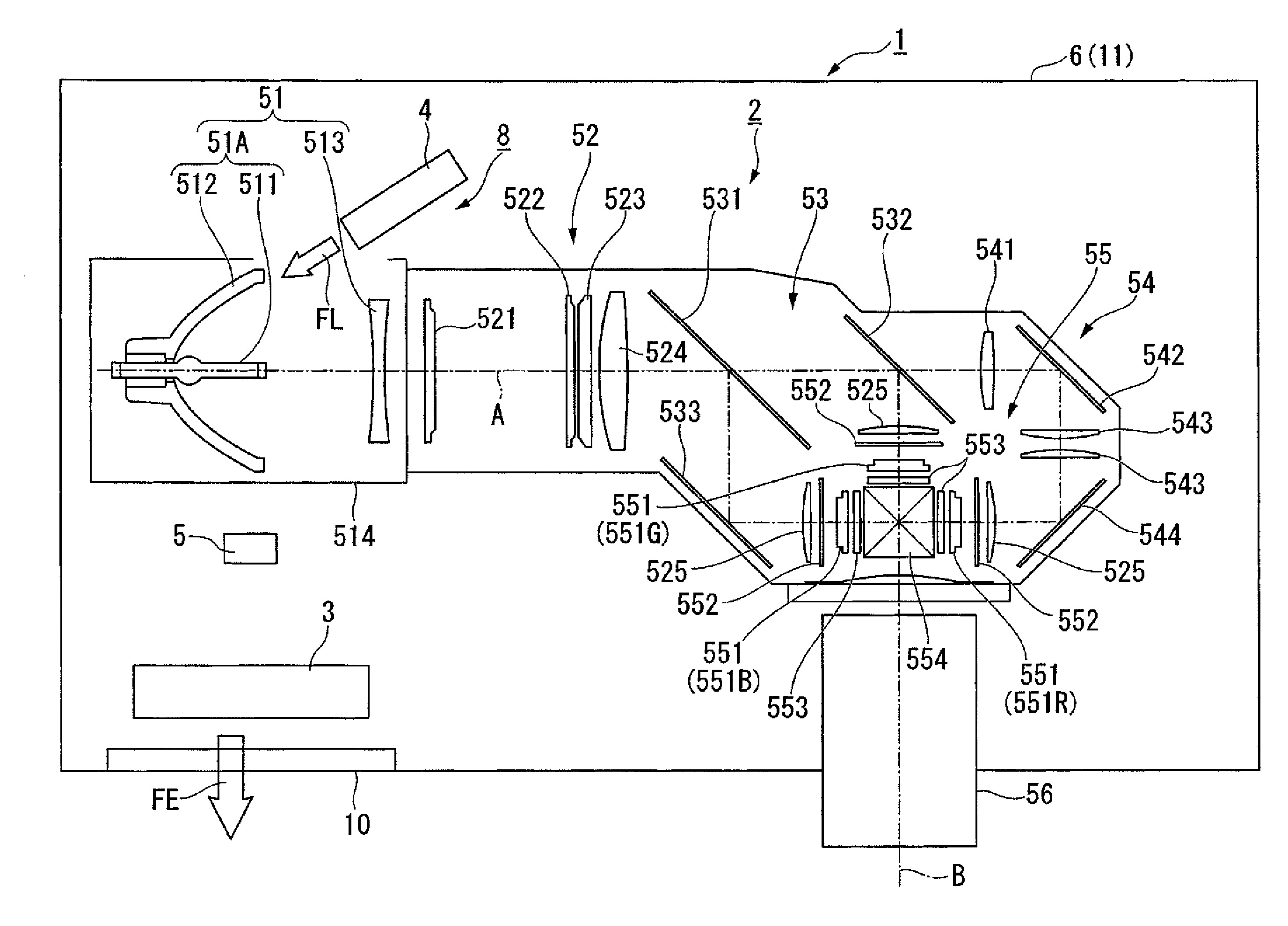
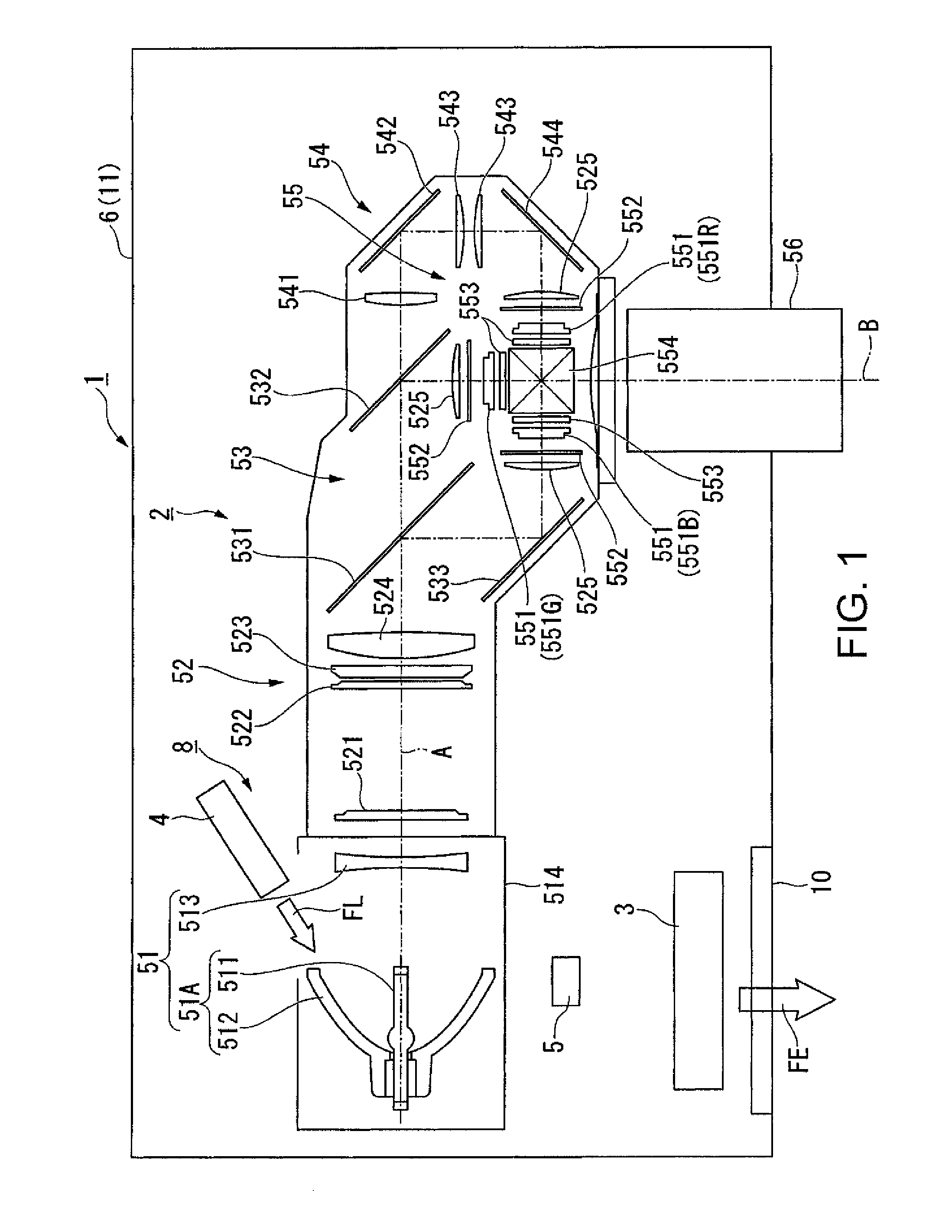
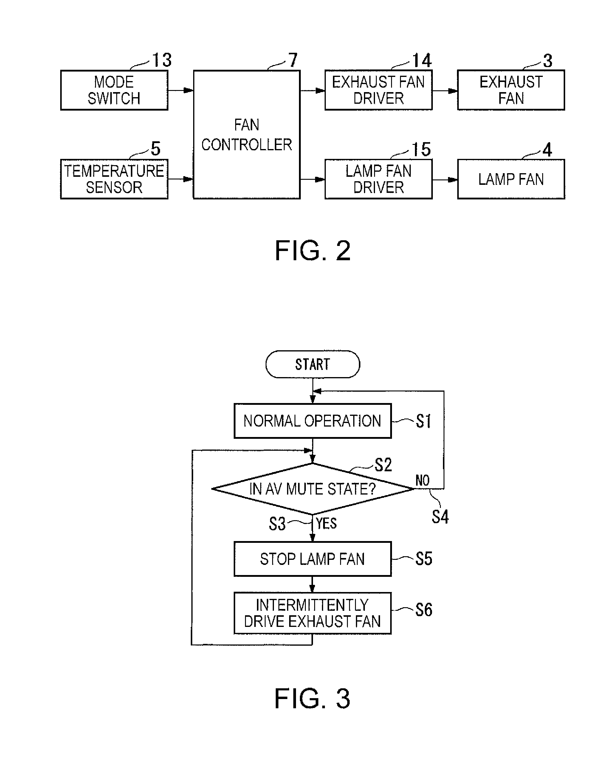
[0037]A projector 1 according to the present embodiment includes an optical unit 2, an exhaust fan 3, a lamp fan 4, a temperature sensor 5, an enclosure 6, and a fan controller 7 (see FIG. 2), as shown in FIG. 1. The optical unit 2 includes an illuminator 8, a color separation optical section 53, alight modulator 55, a light combining optical section 554, and a projection optical section 56. The illuminator 8 is formed of a light source section 51 and a uniform illumination optical section 52.

[0038]The exhaust fan 3 in the present embodiment corresponds to a first fan in the appended claims....

second embodiment

[0084]A second embodiment of the invention will be described below with reference to FIGS. 5, 6A, and 6B.

[0085]The basic configuration of a projector according to the present embodiment is the same as that of the projector according to the first embodiment and differs therefrom only in terms of the method for controlling the exhaust fan.

[0086]In the present embodiment, no description will therefore be made of the configuration of each portion of the projector, and only the method for controlling the exhaust fan will be described.

[0087]In the first embodiment, the fan controller 7 operates the exhaust fan 3 intermittently based on the switching program according to which the operation of the exhaust fan 3 is switched. In contrast, in the present embodiment, the fan controller 7 operates the exhaust fan 3 intermittently based on a temperature detection result detected with the temperature sensor 5. That is, in the first embodiment, no temperature detection result detected with the tem...


PUM


Abstract

A projector includes an optical part including a light source section that outputs light, a light modulator that modulates the light outputted from the light source section based on an image signal, a projection optical section that projects the modulated light from the light modulator, a first fan that cools the optical part, and a fan controller that controls the first fan, and the fan controller operates the first fan intermittently when the light source section outputs light of luminance lower than luminance corresponding to normal image display.

Description

BACKGROUND[0001]1. Technical Field[0002]The present invention relates to a projector and a method for controlling the projector.[0003]2. Related Art[0004]Conventionally, a projector includes an exhaust fan for exhausting air in an enclosure of the projector. The reason for this is that an increase in temperature in the enclosure due to use of a high-intensity lamp lowers the performance of optical parts that form a liquid crystal panel, a polarization conversion system, a color separation / light combining system, and other optical systems. For example, JP-A-2003-5289 discloses a projector that includes an exhaust fan and an intake fan and controls the rotational speeds of the exhaust fan and the intake fan in accordance with the temperature of sucked outside air detected with a temperature sensor.[0005]In recent years, power consumption of projectors has been continuously reduced. To this end, a projector having what is called a power saving mode is provided. In the power saving mode...

Claims


Application Information

Patent Timeline
IPC IPC(8): G03B21/16
CPCG03B21/16F21V29/60H04N9/3144H04N9/3155
Inventor MIYATA, TAKAHIRO
Owner SEIKO EPSON CORP
Learn More