
In-cell capacitive touch panel LCD module and method for driving the same

a capacitive touch panel and capacitive technology, applied in the field of touch sensing and liquid crystal display, can solve the problems of poor optical performance of the display screen 20/b>, low yield, complex production process, etc., and achieve the effect of improving the signal-to-noise ratio of the existing in-cell touch panel

Active Publication Date: 2014-04-24
SHANGHAI TIANMA MICRO ELECTRONICS CO LTD
View PDF5 Cites 26 Cited by
  • Summary
  • Abstract
  • Description
  • Claims
  • Application Information

AI Technical Summary

Benefits of technology

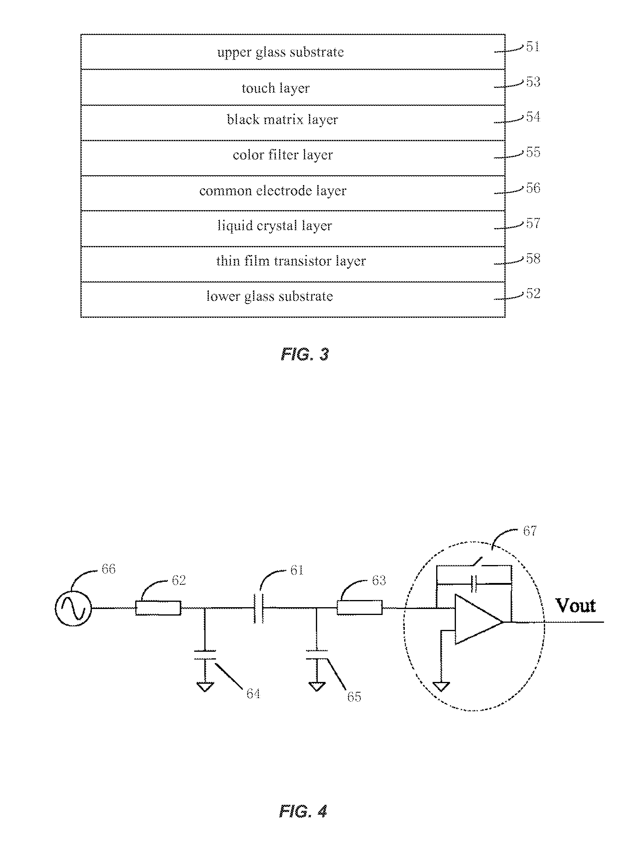
This patent describes an improvement to existing in-cell touch panels to increase the signal-to-noise ratio. By using a portion of the common electrode layer to shield noise interference from the liquid crystal screen, the touch panel becomes more reliable and sensitive. This is achieved by applying a first touch control signal to one common electrode and a second touch control signal to the other common electrode during the touch control time period, which causes the first common electrode to have an electric potential equal to that of the driving line and the second common electrode to have an electric potential equal to that of the sensing line. This eliminates the need for an additional shielding layer and simplifies the structure of the touch panel apparatus.

Problems solved by technology

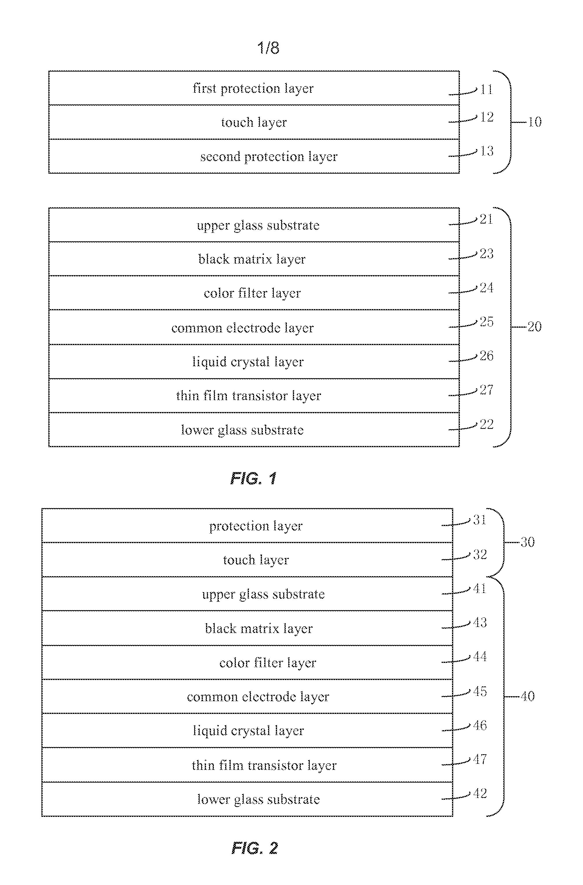
The touch panel 10 is an outboard touch panel, and the display screen 20 has poor optical performance due to the complex structure and large thickness of the touch panel 10.
The on-cell touch panel has the advantage of small noise interference, but also has complex production process and low yield compared with the in-cell touch panel.
However, the touch layer is very close to the common electrode layer in the existing in-cell capacitive touch panel LCD apparatus, and the touch panel is sensing the touch control signal from the user while the LCD screen is displaying images frame by frame, therefore, the touch panel is likely be affected by the electrical noise generated by the LCD screen, leading to a low signal-to-noise ratio of the touch panel.

Method used


Image

  • In-cell capacitive touch panel LCD module and method for driving the same
  • In-cell capacitive touch panel LCD module and method for driving the same
  • In-cell capacitive touch panel LCD module and method for driving the same

Examples


Embodiment Construction

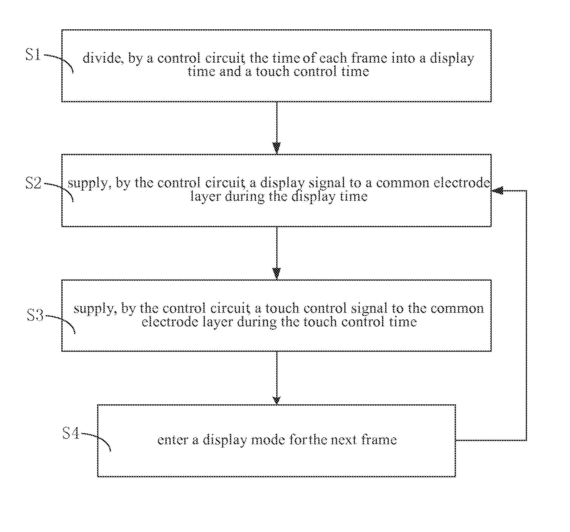
[0042]In order to solve the problem of low signal-to-noise ratio of the conventional in-cell touch panels, embodiments of the present invention provide an in-cell touch panel liquid crystal display (LCD) module and a method for driving the same. The in-cell touch panel LCD module includes a common electrode layer, a driving line and a sensing line. The common electrode layer includes at least two common electrodes, a first common electrode and a second common electrode. At least a portion of the driving line overlaps with the first common electrode and at least a portion of the sensing line overlaps with the second common electrode. A display signal is applied to the common electrode layer during a display time, and the LCD screen displays an image accordingly. A first touch control signal is applied to the first common electrode and a second touch control signal is applied to the second common electrode during a touch control time, to make the electric potential of the first common...


PUM


Abstract

An in-cell touch panel LCD module (100) and a method for driving the same includes a common electrode layer including first and second common electrodes. A control circuit divides the frame time period into a display time period and a touch control time period. A display signal is applied to the common electrode layer during the display time period for a normal LCD display. First and second touch control signals are applied to the first and second common electrodes, respectively, during the touch control time period, so that the electric potential of the first common electrode equals to that of the driving line and the electric potential of the second common electrode equals to that of the sensing line.

Description

CROSS-REFERENCES TO RELATED APPLICATIONS[0001]This application claims priority to and is a continuation of PCT / CN2012 / 086192, filed on Dec. 7, 2012, entitled “IN-CELL CAPACITIVE TOUCH PANEL LCD MODULE AND METHOD FOR DRIVING THE SAME”, which claims the benefit of Chinese patent application No. 201210365235.1, filed with the Chinese Patent Office on Sep. 26, 2012, entitled “IN-CELL CAPACITIVE TOUCH PANEL LCD MODULE AND METHOD FOR DRIVING THE SAME”, the contents of which are incorporated herein by reference in their entirety.FIELD OF THE INVENTION[0002]The present invention relates to the field of touch sensing and liquid crystal display (LCD), and in particular to an in-cell capacitive touch panel LCD module and a method for driving the same.BACKGROUND OF THE INVENTION[0003]Touch panels are touch-sensing input apparatuses, which are widely used. The most commonly known types of touch panels include resistive touch panels, capacitive touch panels, surface infrared touch panels, and the...

Claims


Application Information

Patent Timeline
IPC IPC(8): G02F1/1333G06F3/044
CPCG06F3/044G02F1/13338G02F2201/121G06F3/0412G06F3/04166G06F3/0443G06F2203/04107G09G3/3655G09G2300/0426
Inventor YOU, SHUAIMA, JUNMA, CONGHUAYAO, QIJUN
Owner SHANGHAI TIANMA MICRO ELECTRONICS CO LTD
Learn More