
Mounting and installing system for solar photovoltaic modules and arrays

a solar photovoltaic and array technology, applied in the direction of photovoltaics, heat collector mounting/support, solar heat collector safety, etc., can solve the problem that the inclination of the PV module directly affects the overall performance, and achieve the effect of quick installation and reduced forces on the solar photovoltaic system

Inactive Publication Date: 2014-04-24
KB RACKING
View PDF8 Cites 12 Cited by
  • Summary
  • Abstract
  • Description
  • Claims
  • Application Information

AI Technical Summary

Benefits of technology

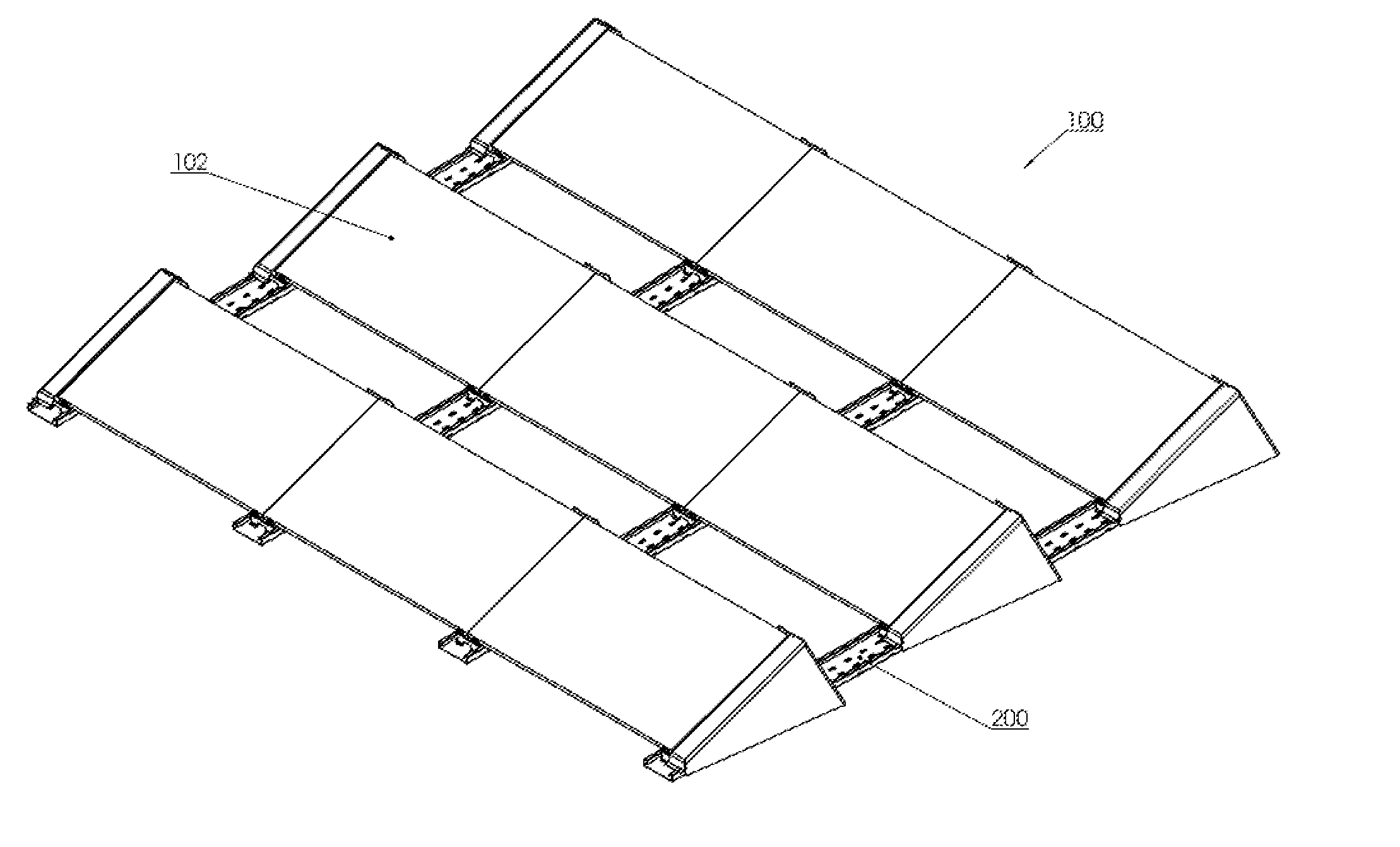
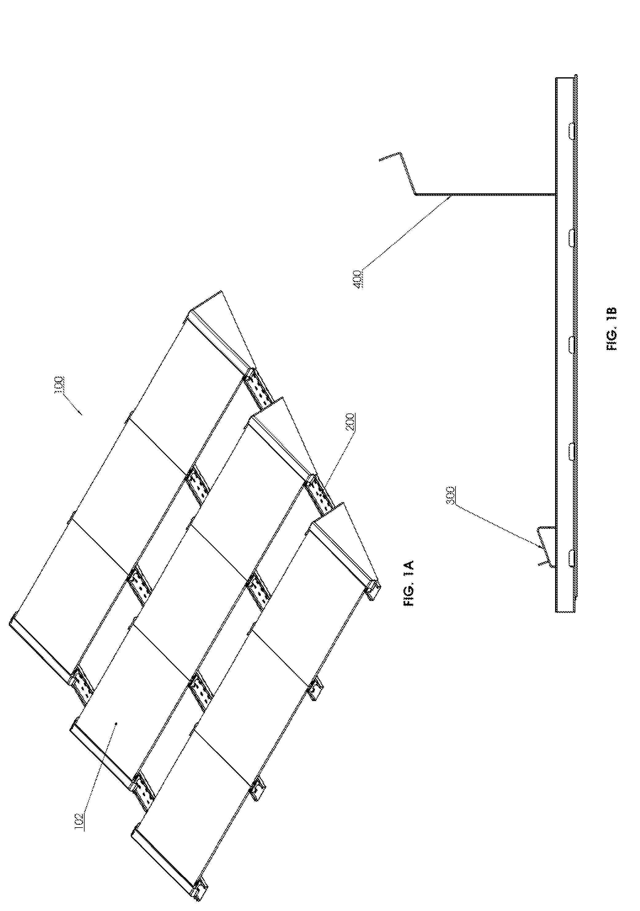
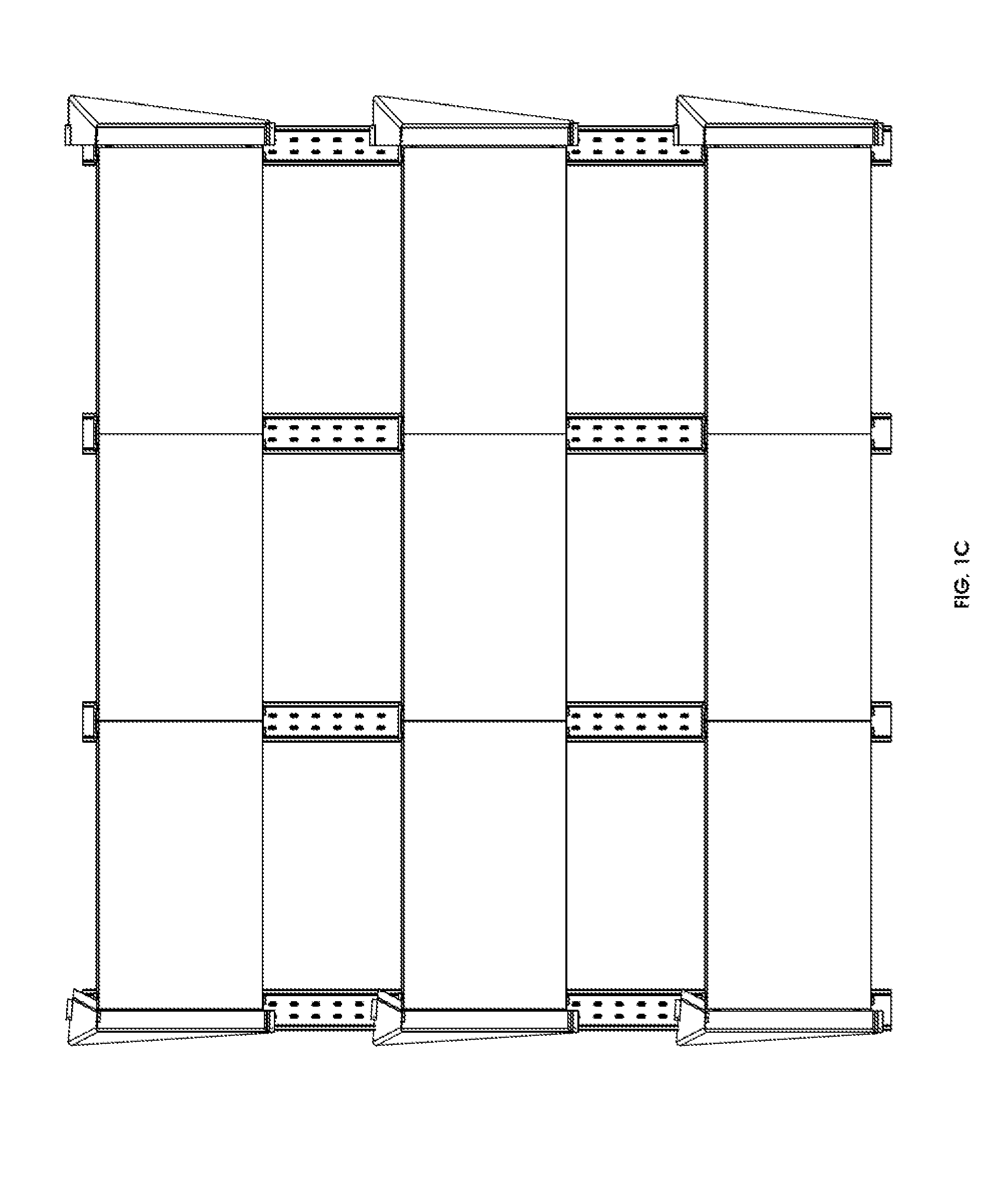
The present invention provides a system for mounting and installing solar photovoltaic modules and arrays for low-slope rooftops that is lightweight, quick to install, and aerodynamic. The system includes a rail structure that provides a rigid linking platform to interconnect solar photovoltaic modules. The modules are secured atop a bottom and top link member by a module mounting clamp, which can also ground the modules. The system also includes a rear and flanking wind deflector to reduce forces acting on the system. The wind deflector members are secured using self-drilling machine thread screws to provide a bonding connection. The invention allows for the interconnection of solar photovoltaic modules, providing structural strengths and ballasting throughout the solar photovoltaic array. The method also allows for a self-ballasting solar photovoltaic system that reduces additional load requirements on the roof. The system is easy to install and can be easily adapted to different roof conditions.

Problems solved by technology

Similarly, the tilt angle at which a PV module is inclined directly affects the overall performance thereof throughout each day.
An ideal racking system must be both lightweight and aerodynamic because many rooftops are not designed to carry additional dead loads.

Method used


Image

  • Mounting and installing system for solar photovoltaic modules and arrays
  • Mounting and installing system for solar photovoltaic modules and arrays
  • Mounting and installing system for solar photovoltaic modules and arrays

Examples


Embodiment Construction

[0040]As required, detailed embodiments of the present invention are disclosed herein; however, it is to be understood that the disclosed embodiments are merely exemplary of the invention, which can be embodied in various forms. Therefore, specific structural and functional details disclosed herein are not to be interpreted as limiting, but merely as a basis for the claims and as a representative basis for teaching one skilled in the art to variously employ the present invention in virtually any appropriately detailed structure. Further, the terms and phrases used herein are not intended to be limiting but rather to provide an understandable description of the invention.

[0041]Turning now descriptively to the drawings, in which similar reference characters denote similar elements throughout the several views, the figures illustrate a system for mounting and installing of solar photovoltaic modules and arrays, in accordance with various embodiments of the present invention. The system...


PUM


Abstract

A system for mounting and installing of solar photovoltaic modules is provided. The system is a lightweight, quick to install, and aerodynamic mounting system for integrating solar photovoltaic modules and solar photovoltaic arrays for low-slope rooftops. The mounting and installing of solar photovoltaic modules includes a rubber mat, a rail member positioned atop the rubber mat, a link member coupling multiple rails, a bottom link member and a top link member coupled to a rail member, a rear wind deflector coupled to a top link member, a flanking wind deflector coupled to a top link member and a rail member.

Description

BACKGROUND OF THE INVENTION[0001]1. Field of the Invention[0002]The present invention relates generally to a system for integrating and mounting solar photovoltaic modules and arrays, and more specifically, the present invention relates to a lightweight, quick to install and aerodynamic mounting system for integrating solar photovoltaic modules and solar photovoltaic arrays for low-slope rooftops.[0003]2. Description of the Related Art[0004]Solar irradiance is the most ample source of energy on this planet, which maintains the majority of all life on earth. Being able to harness the abundant solar energy and convert it into usable electricity is one of the main contributors behind the growth of the solar photovoltaic industry.[0005]As the industry continues to grow and the technology advances, solar photovoltaic modules (“PV Modules”) become increasingly popular, and so do the means by which they are utilized. Countries all over the world encourage their populace to contribute and g...

Claims


Application Information

Patent Timeline
IPC IPC(8): H01L31/048
CPCF24S25/13F24S25/16F24S40/85F24S2025/804H02S20/24Y02B10/10Y02E10/50
Inventor AULICH, PETER
Owner KB RACKING
Learn More