Surface roughness measuring unit and coordinate measuring apparatus
a technology of surface roughness and measuring unit, which is applied in the direction of mechanical roughness/irregularity measurement, measurement device, instruments, etc., can solve the problems the contact pin unit inevitably oscillates in a direction, and it is unlikely that a determination can be made as to whether a measurement is made, so as to achieve the effect of lowering the measurement efficiency
- Summary
- Abstract
- Description
- Claims
- Application Information
AI Technical Summary
Benefits of technology
Problems solved by technology
Method used
Image
Examples
first embodiment
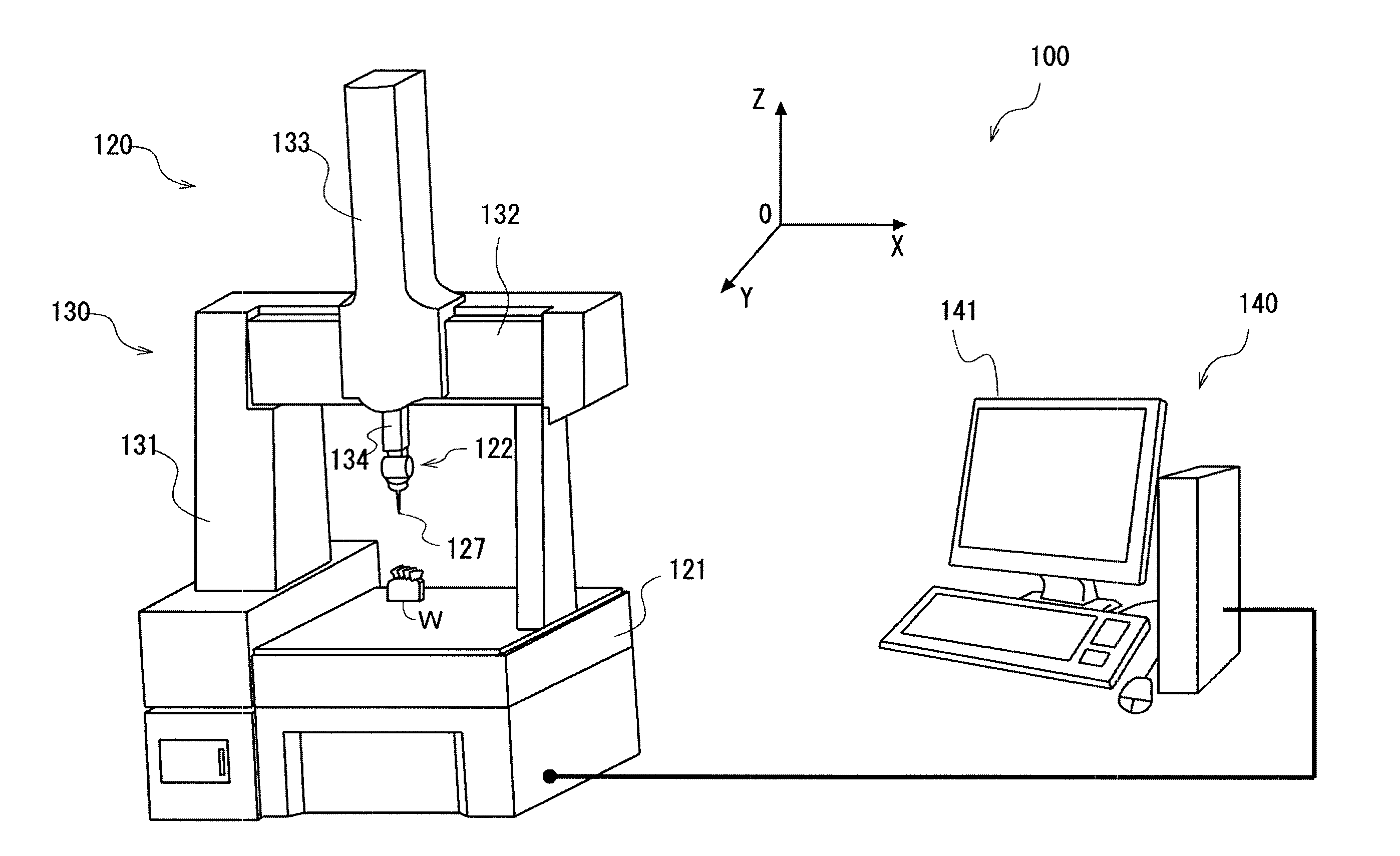
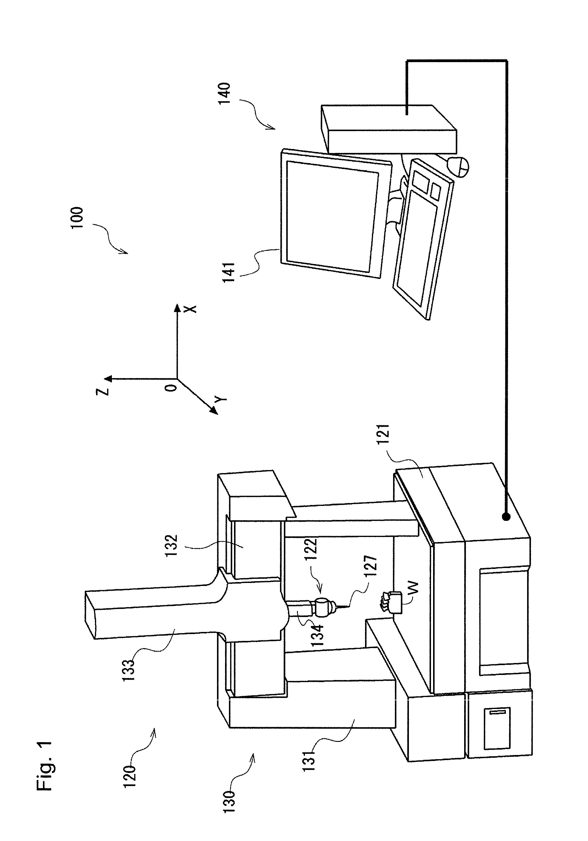
[0035]A surface roughness measuring unit according to a first embodiment of the present invention is described. The surface roughness measuring unit can be coupled to the moving mechanism 130 of the coordinate measuring system 100 and used instead of the touch sensor probe. In the following, embodiments of the present invention are described with reference to the drawings.
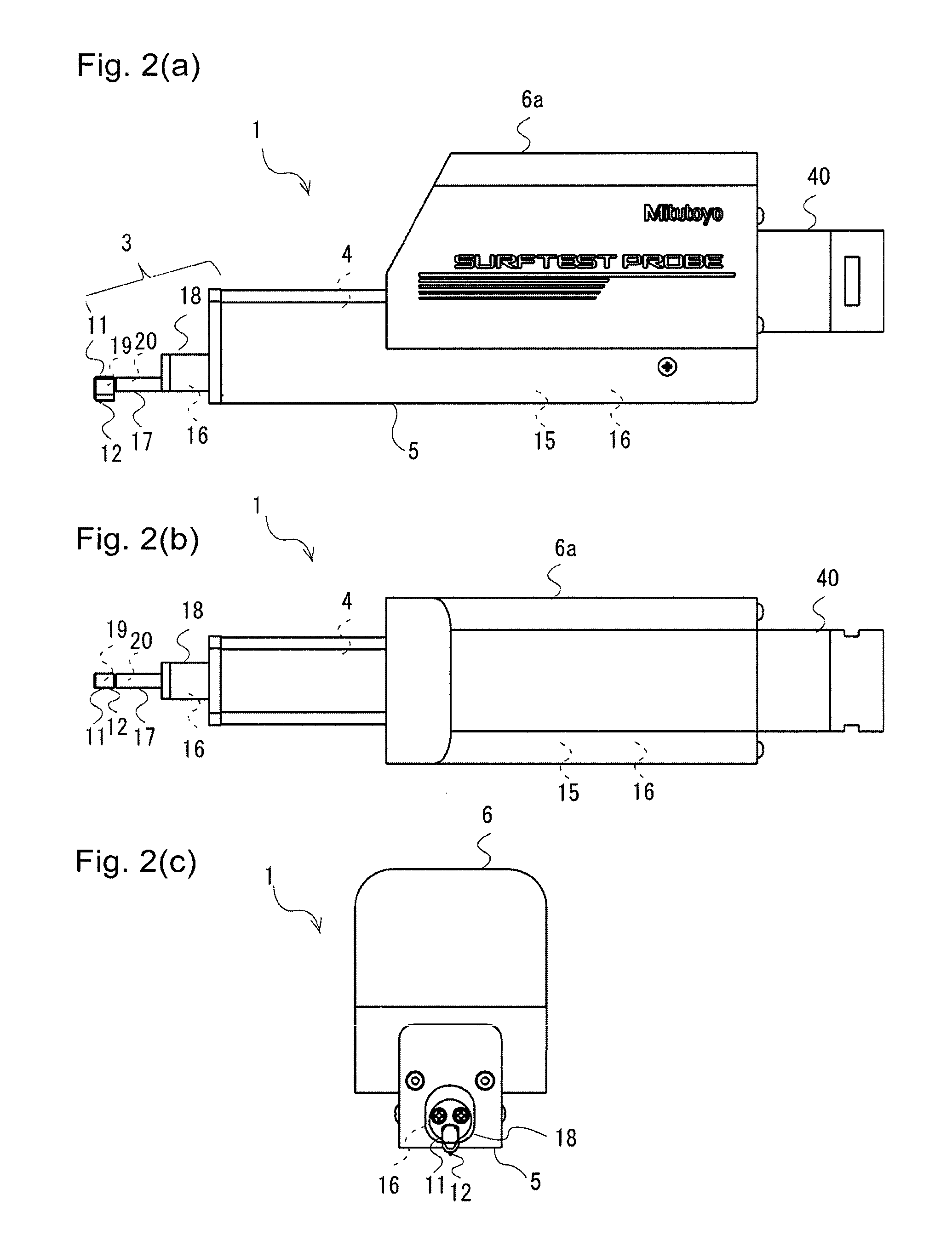
[0036]FIG. 2(a) is a side view of a surface roughness measuring unit 1. FIG. 2(b) is a top view of the surface roughness measuring unit 1. FIG. 2(c) is a front view of the surface roughness measuring unit 1.
[0037]The surface roughness measuring unit 1 includes a contact pin unit 3, a driver 4, a second supporter 6, and a joint 40. The surface roughness measuring unit 1 is coupled to the moving mechanism 130 (specifically, the bottom end of the Z-axis spindle) by the joint 40. (The second supporter 6 is connected to the joint 40 to link the contact pin unit 3 and the driver 4 to the joint 40. Details will be describ...
second embodiment
[0057]The surface roughness measuring unit 1 of the present invention further includes a collision detector 50 in addition to the contact detector described in the first embodiment. The collision detector 50 detects that the surface roughness measuring unit 1, rather than the skid 11, has collided with an unexpected obstacle.
[0058]The contact pin unit 3 of the surface roughness measuring unit 1 needs to perform highly precise parallel displacement. Thus, a positional relationship among the skid 11, the guide 26, and the driving mechanism 24 is restricted to some extent, and theretofore, it is unavoidably difficult to secure a sufficient gap between the bottom end surface of the skid 11 and the bottom surface of the driver casing 5. For example, as shown in FIGS. 2(a) to 2(c), the bottom end of the skid 11 and the bottom surface of the driver casing 5 are often approximately level with each other. Thus, in a case where unevenness or a projection is left on the surface of the work pie...
PUM
 Abstract
Description
Claims
Application Information
 - R&D
- Intellectual Property
- Life Sciences
- Materials
- Tech Scout
- Unparalleled Data Quality
- Higher Quality Content
- 60% Fewer Hallucinations
Browse by: Latest US Patents, China's latest patents, Technical Efficacy Thesaurus, Application Domain, Technology Topic, Popular Technical Reports.
© 2025 PatSnap. All rights reserved.Legal|Privacy policy|Modern Slavery Act Transparency Statement|Sitemap|About US| Contact US: help@patsnap.com


