
Bi-directional dc/dc converter

Active Publication Date: 2014-04-17
FUJI ELECTRIC CO LTD
View PDF6 Cites 23 Cited by
  • Summary
  • Abstract
  • Description
  • Claims
  • Application Information

AI Technical Summary

Benefits of technology

The present invention introduces a DC / DC converter that can deliver a wider range of voltages during conversion of DC voltage between two sources. This results in improved performance for applications such as battery chargers.

Problems solved by technology

As a result, semiconductor switching elements composing the second bridge circuit 19 are necessarily semiconductor switching elements with high withstand voltage, which generally produce large loss.
This causes a problem of low efficiency of the device.
Therefore, it can be hard to apply the bi-directional DC / DC converter of FIG. 5 to devices with a wide range of input / output voltage, such as battery chargers.[Patent Document 1]
Therefore, it can be hard to apply a resonance type bi-directional DC / DC converter using pulse frequency modulation control to devices with a wide range of input / output voltage.

Method used


Image

  • Bi-directional dc/dc converter
  • Bi-directional dc/dc converter
  • Bi-directional dc/dc converter

Examples


Embodiment Construction

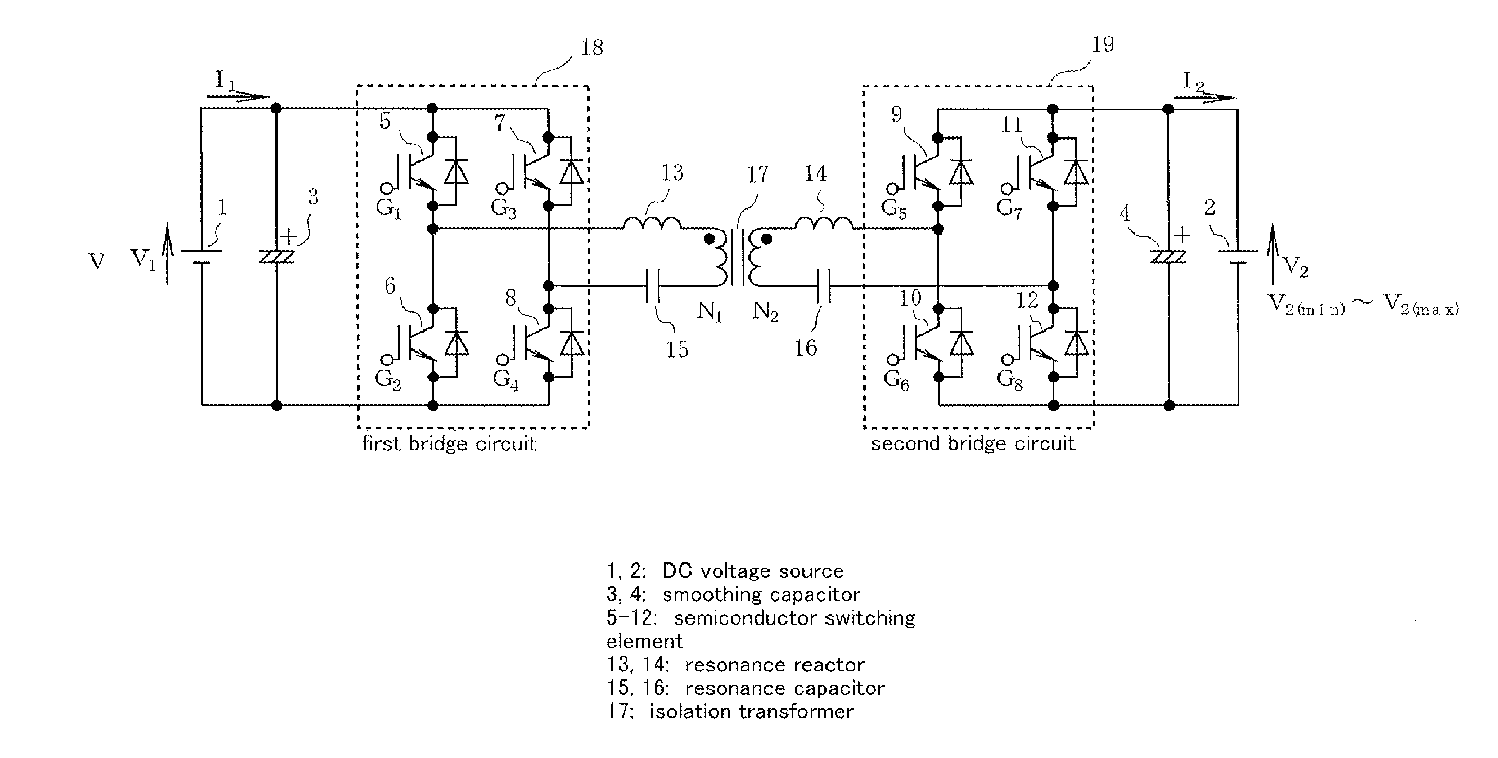
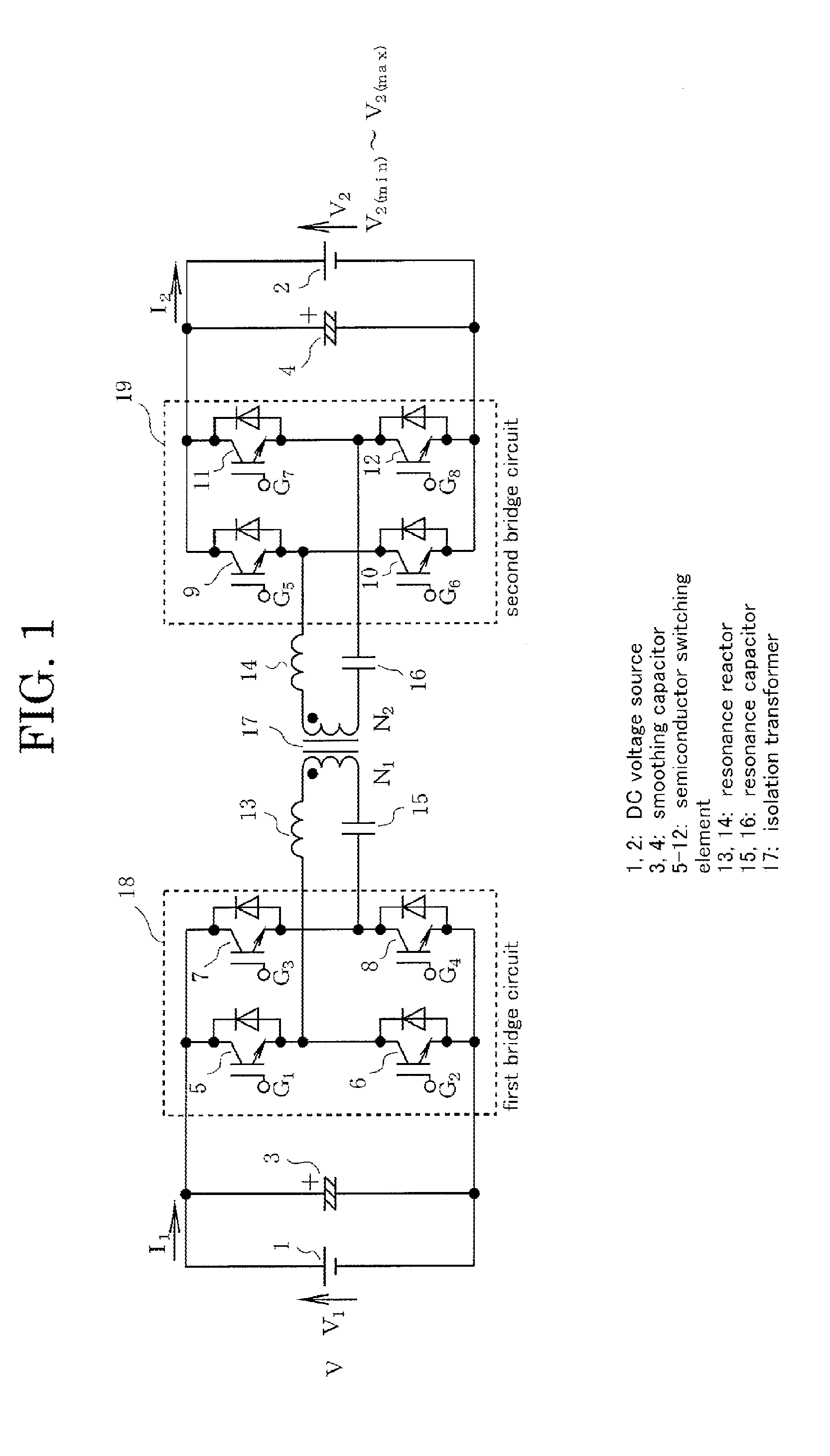
[0049]The following describes some illustrative embodiments of the present invention with reference to accompanying drawings. FIG. 1 shows an example of construction of a main circuit of a resonance type bi-directional DC / DC converter according to an embodiment of the invention. Although this main circuit is the same as the one shown in FIG. 4, explanation is made again in the following in order to clarify the circuit construction.

[0050]Referring to FIG. 1, the both terminals of a parallel-connected circuit of a first DC voltage source 1 (voltage of which is V1) and a smoothing capacitor 3 are connected to a pair of DC terminals of a first bridge circuit 18. The bridge circuit 18 is composed of IGBTs 5 through 8 each having an anti-parallel-connected diode. Between a pair of AC terminals, a resonance reactor 13, a primary winding N1 of an isolation transformer 17, and a resonance capacitor 15 are connected in series.

[0051]A terminal of a secondary winding N2 of the isolation transfo...


PUM


Abstract

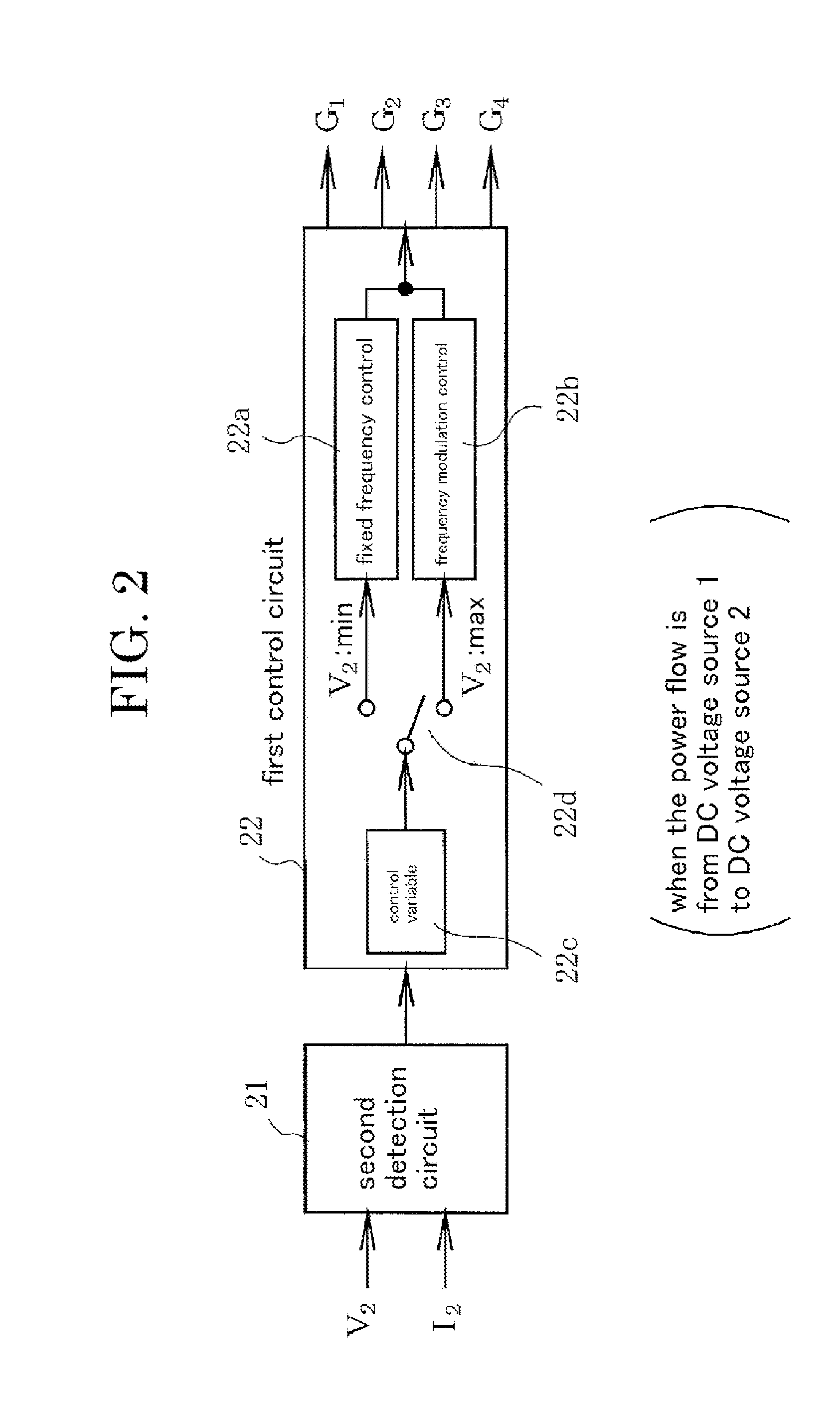
A bi-directional DC / DC converter comprises bridge circuits connected to DC voltage sources, an isolation transformer, an LC resonance circuit, and detection circuits for detecting voltages and currents of the DC voltage sources. A control circuit in the power flow from a first DC voltage source to a second DC voltage source changes over between fixed frequency control and frequency modulation control according to the magnitude of a control variable, and a control circuit in the power flow from a second DC voltage source to the first DC voltage source changes over between fixed frequency control and frequency modulation control according to the magnitude of another control variable. Thus, the bi-directional DC / DC converter can be applied to devices with a wide range of input and output voltages.

Description

CROSS-REFERENCE TO RELATED APPLICATION[0001]This application is based on, and claims priority to, Japanese Patent Application No. 2012-226966, filed on Oct. 12, 2012, contents of which are incorporated herein by reference.BACKGROUND OF THE INVENTION[0002]1. Field of the Invention[0003]The present invention relates to a bi-directional DC / DC converter of an isolation type and resonance type applied to devices with a wide range of input and output voltage, such as a battery charger.[0004]2. Description of the Related Art[0005]FIG. 4 shows a traditional bi-directional DC / DC converter of an isolation type. The bi-directional DC / DC converter comprises: a first DC voltage source 1 with a DC voltage of V1, a second DC voltage source with a DC voltage of V2, smoothing capacitors 3 and 4, an isolation transformer 17, a first bridge circuit 18, a second bridge circuit 19, and a smoothing reactor 24. The transformer 17 has a primary winding N1 and a secondary winding N2, the numbers of winding ...

Claims


Application Information

Patent Timeline
IPC IPC(8): H02M3/335
CPCH02M3/33584H02M3/3376Y02B70/10H02M1/0058H02M7/4815
Inventor MATSUBARA, KUNIONISHIKAWA, YUKIHIRO
Owner FUJI ELECTRIC CO LTD
Learn More