
Substrate transfer system and substrate positioning device

a technology of substrate positioning and transfer system, which is applied in the direction of conveyors, mechanical conveyors, conveyors, etc., can solve problems such as and achieve the effect of reducing the risk of fragmentation

Inactive Publication Date: 2014-04-17
SHENZHEN CHINA STAR OPTOELECTRONICS TECH CO LTD
View PDF10 Cites 6 Cited by
  • Summary
  • Abstract
  • Description
  • Claims
  • Application Information

AI Technical Summary

Benefits of technology

The present invention solves the technical problem of positioning deviation and risk of fragmentation of a substrate during transfer and positioning. The invention includes a buffer reset mechanism for controlling the position of the positioning pole, providing buffered contact for the substrate to eliminate the risk of fragmentation. Additionally, the sensor of the buffer reset mechanism can be used for detecting various conditions, such as force applied to the positioning pole, rotational speed stability, and surface abrasion condition, for long-term monitoring and control.

Problems solved by technology

However, the existing substrate transfer system has the following disadvantages at least: 1. because the limit pole 9 is fixedly arranged, the glass substrate 1 is inclined to be fragmented when colliding with the limit pole 9; 2. when the glass substrate 1 goes beyond the predetermined position, the positioning sensor 8 cannot detect it, thus causing the position deviation, proceeding with flowing in this case having a risk of fragmentation; and 3. after the glass substrate 1 is stopped, the limit pole 9 moves over for correcting and confirming the position, during which the glass substrate 1 collides rigidly with the limit pole 9, causing a risk of fragmentation.

Method used


Image

  • Substrate transfer system and substrate positioning device
  • Substrate transfer system and substrate positioning device
  • Substrate transfer system and substrate positioning device

Examples


Embodiment Construction

[0052]The present invention will further be explained with reference to drawings and embodiments.

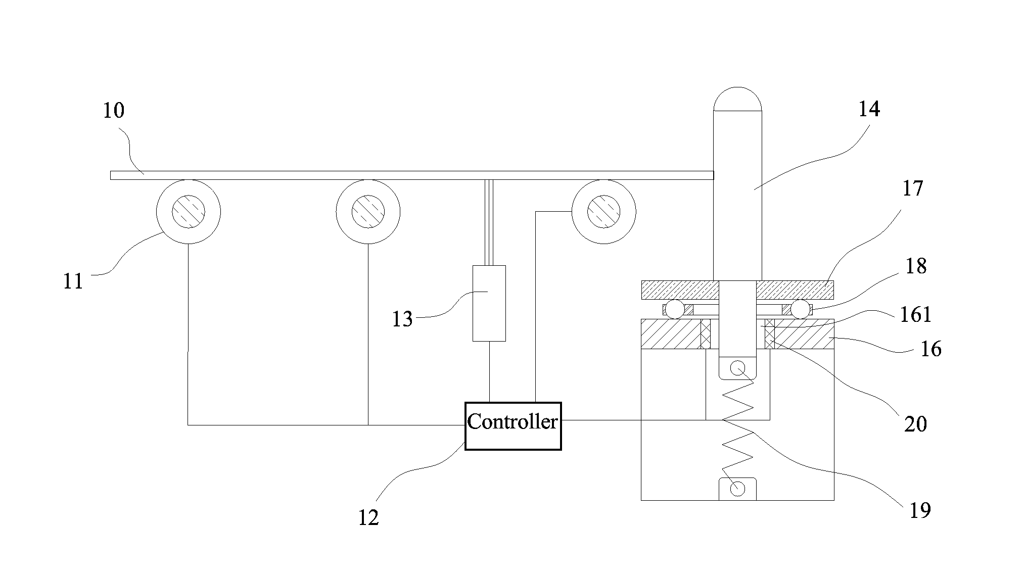
[0053]FIGS. 3-10 show an example of the substrate transfer system and the substrate positioning device of the present invention, wherein this substrate transfer system comprises roller assemblies 11, a controller 12, a substrate positioning device, and etc., and can be used in the manufacturing process of the liquid crystal panel. It can be understood that the roller assemblies 11, the controller 12, the substrate positioning device, etc. can be arranged on the same frame, different frames or other equipments.

[0054]Various existing roller assemblies 11 can be used in the roller assemblies 11 for supporting the glass substrate 10 to be transferred thereon. And the controller 12, connected to the roller assemblies 11, controls rotational speed, start and stop, etc. of the roller assemblies 11, thus controlling the transfer of the glass substrate 10.

[0055]In this example, the roller assembl...


PUM


Abstract

The present invention relates to a substrate transfer system, comprising a number of roller assemblies used for mobile transfer of the glass substrate on it, and a controller used for controlling rotation of the roller assemblies; the substrate transfer system further comprises a substrate positioning device, which is arranged at the end of the transfer direction of the glass substrate by the roller assemblies; the substrate positioning device comprises a positioning pole, which is used for blocking and positioning the glass substrate transferred by the roller assemblies; and a buffer positioning mechanism on which the positioning pole is mounted on, providing mobile buffer for the positioning pole and driving the positioning pole to reset. A buffer reset mechanism is arranged for controlling the position of the positioning pole, and the positioning deviation of the substrate can be further eliminated; it can provide buffer contact for eliminating the risk of fragmentation.

Description

FIELD OF THE INVENTION[0001]The present invention relates to the field of liquid crystal panel manufacture, and more particularly to a substrate transfer system and a substrate positioning device that can be used for liquid crystal panel manufacture.BACKGROUND OF THE INVENTION[0002]During the liquid crystal panel manufacturing process, the glass substrate 1 is usually transferred by a substrate transfer system. The existing substrate transfer system usually comprises a frame 5, a number of roller assemblies arranged side by side, and a controller 6 for controlling the roller assembly 6.[0003]As shown in FIG. 1, the roller assembly comprises a drive motor 2, a shaft 3 driven by the drive motor 2, and a roller 4 sleeved on the shaft 3. The controller 6 is used to control rotation of the drive motor 2, so as to drive the shaft 3 to rotate, drive the roller 4 to rotate, and then drive the glass substrate 1 placed on the roller 4 to go forward by the friction of the roller 4, thus transf...

Claims


Application Information

Patent Timeline
IPC IPC(8): B65G13/075
CPCB65G13/075H01L21/67706H01L21/68H01L21/6776
Inventor WANG, YONGQIANGWU, CHUN HAOLIN, KUN HSIENQI, MINGHUYANG, WEIBINGCHEN, ZENGHONGGUO, ZHENHUAJIANG, YUNSHAOSHU, ZHIYOU
Owner SHENZHEN CHINA STAR OPTOELECTRONICS TECH CO LTD
Learn More