
Electric actuator module for selectable clutch

a technology of selectable clutches and actuator modules, which is applied in the direction of clutches, non-mechanical actuated clutches, freewheel clutches, etc., can solve the problems of not being robust or reliable in locking up, and achieve greater accuracy and control, reduced power consumption and other negative drawbacks, and strong magnetic actuator devices

Active Publication Date: 2014-04-17
MAGNA POWERTRAIN OF AMERICA
View PDF5 Cites 61 Cited by
  • Summary
  • Abstract
  • Description
  • Claims
  • Application Information

AI Technical Summary

Benefits of technology

The present invention provides a better device and control system for the OWC clutch in a vehicle transmission. The improvement involves incorporating the clutch actuator housing into the magnetic circuit that activates the clutch, making it stronger and more precise while reducing power consumption and other negative aspects of existing mechanisms and controls.

Problems solved by technology

While this arrangement is one method of actuating a strut, it requires single pole magnetic attraction which is not as robust or reliable of a lock up as might be desired depending on the application.

Method used


Image

  • Electric actuator module for selectable clutch
  • Electric actuator module for selectable clutch
  • Electric actuator module for selectable clutch

Examples


Embodiment Construction

[0025]In accordance with the present invention there is provided a clutch module generally shown at 10 for example for a transmission (not shown) which is controlled using an on-off relay to actuate a clutch mechanism.

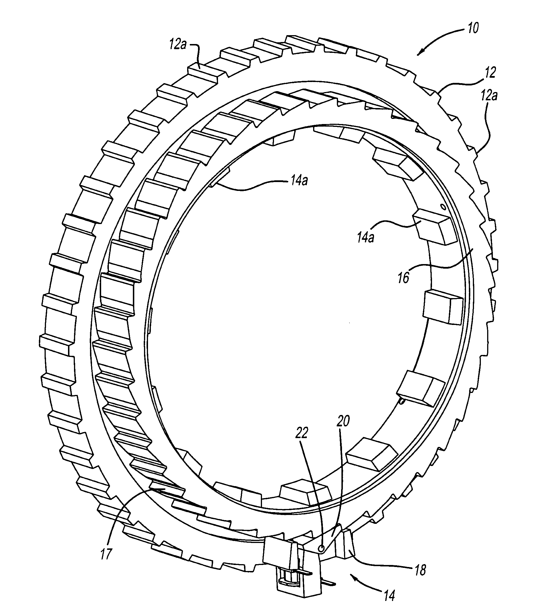
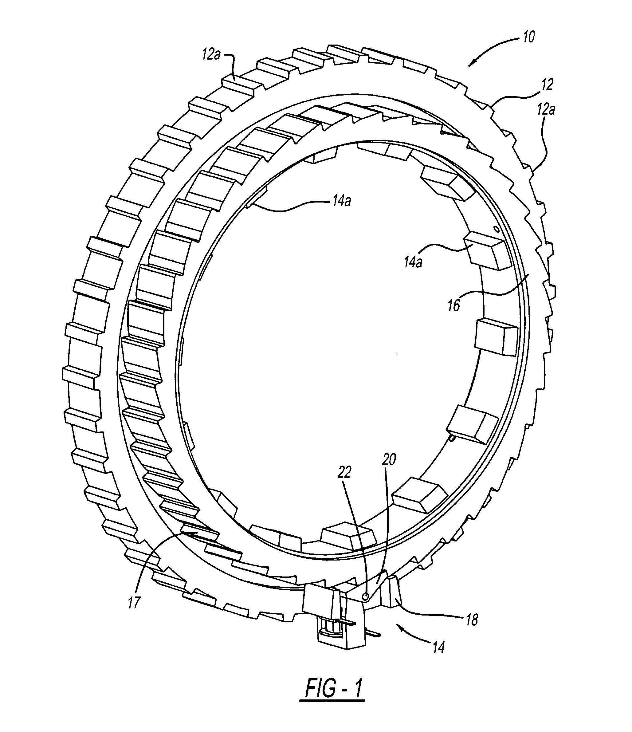
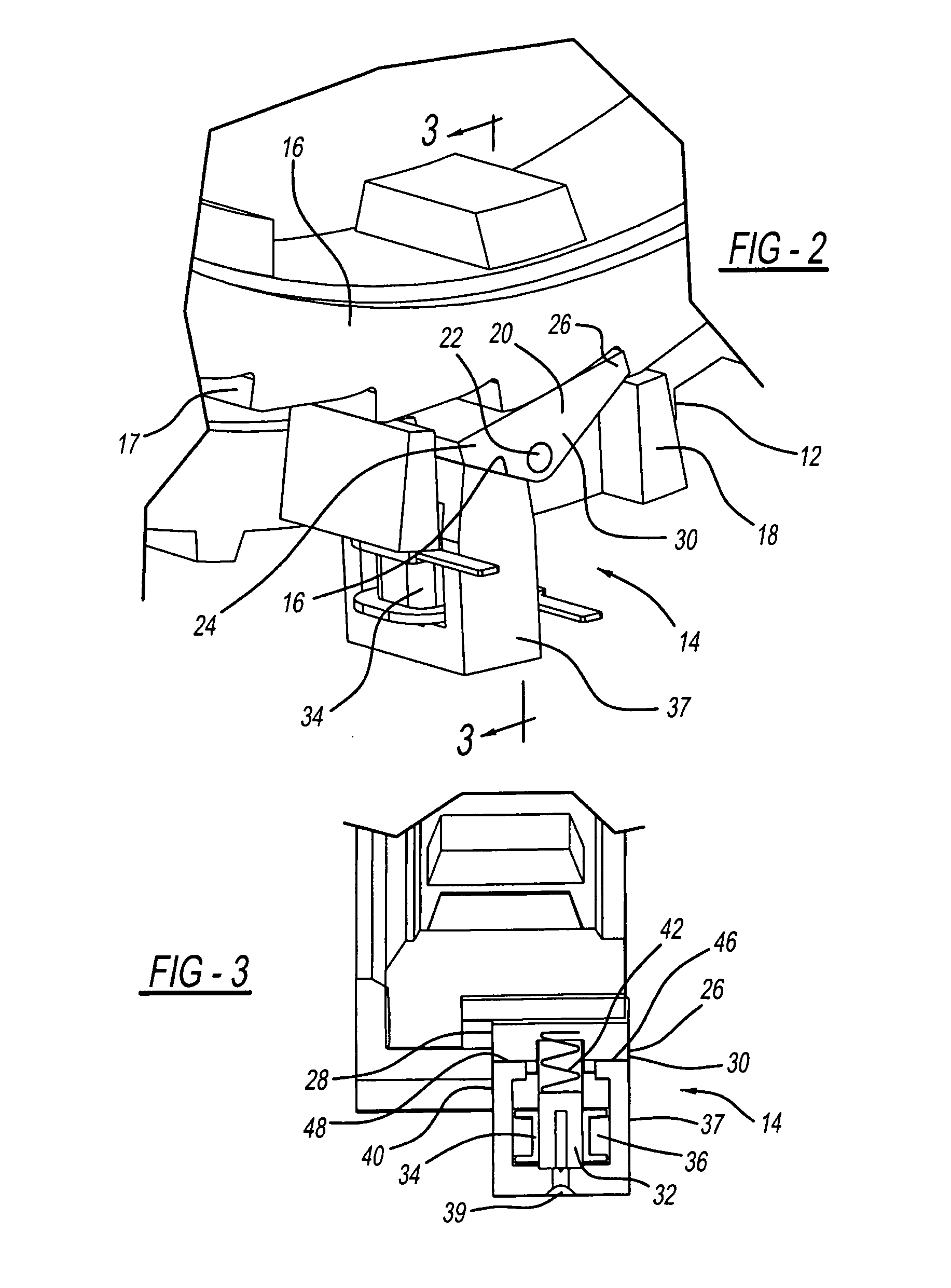
[0026]Referring to the drawings, FIGS. 1-4, there are provided a clutch module 10 which includes a first rotating member 12 including at least one strut actuation module generally indicated as 14 and a second engaged member 16 including cam surfaces 17 thereon for engagement by said strut actuation module 14. The members 12 and 14 include engagement teeth or splines 12(a) and 14(a) respectively. The strut actuation module 14 includes a frame 18 with a strut 20 pivotally movable with respect to frame 18 about a pivot 22. The strut 20 includes an engagement end 26 and a base end 24 and including a first side 28 and a second side 30 thereof. A pin or post portion 32 extends from said frame 18 and has an insulated bobbin 34 with an energizable coil 36 surrounding the bobbi...


PUM


Abstract

A clutch module which includes a first rotating member including at least one strut actuation module and a second engaged member including cam surfaces thereon for engagement by said strut actuation module. The strut actuation module includes a frame with a strut pivotally movable with respect to the frame. The strut includes an engagement end and a base end including a first side and a second side thereof. A pin or post portion extends from the frame and has an insulated bobbin with an energizable coil surrounding the bobbin. A U-shaped member including a pair of actuation legs is attached to the pin member and forms a magnetic gap between the base end of the strut and peripheral ends of the legs, such that when the coil is energized the peripheral ends of the legs are polarized in a first polarity and the frame and the strut are polarized with an opposite polarity thereby biasing the strut toward the peripheral ends and pivoting the actuation end into engagement with a cam surface of the engagement member.

Description

CROSS-REFERENCE TO RELATED APPLICATIONS[0001]This application claims the benefit of U.S. Provisional Application No. 61 / 715,121, filed Oct. 17, 2012 which is incorporated herein by reference thereto.FIELD OF THE INVENTION[0002]The present disclosure relates generally to an actuation member. More particularly, the present disclosure relates to a transmission for use in a drive train of a vehicle (such as an automobile truck, van, utility, industrial equipment, fleet, cargo or the like) including an actuation member for use in selectively a clutch in the transmission.BACKGROUND OF THE INVENTION[0003]A selectable one way clutch (OWC) to be used in automatic transmissions replaces the friction discs OWC actuated by oil pressure with a strut-based selectable OWC actuated by an electromagnetic module controlled by the transmission ECU. This reduces the drag losses associated with the friction disc clutch of prior designs when it is open and over-running continuously while the transmission...

Claims


Application Information

Patent Timeline
IPC IPC(8): F16D48/06
CPCF16D48/064F16D41/12F16D41/16F16D27/09F16D41/08F16D27/00
Inventor GREENE, DARRELLCIOC, ADRIAN
Owner MAGNA POWERTRAIN OF AMERICA
Learn More