
Shift lever operation structure

a technology of operation structure and shift lever, which is applied in the direction of mechanical equipment, gearing control, transportation and packaging, etc., can solve the problems of affecting the operation of shift lever, and affecting the commercial value of the vehicle, so as to prevent excessive loose and excessive tight connections and smooth operation of the shift lever

Inactive Publication Date: 2014-04-17
HYUNDAI MOTOR CO LTD +1
View PDF9 Cites 0 Cited by
  • Summary
  • Abstract
  • Description
  • Claims
  • Application Information

AI Technical Summary

Benefits of technology

The present invention provides a shift lever operation structure that removes gaps at connection parts between a shift plate and an engaging plate to prevent excessive loose or tight connections, giving a smooth operation for the driver. The structure includes a shift plate, an engaging plate, and an elastic member assembled with the connection part of the engaging plate. The elastic member is curved at its inner sides towards the interior space and has hook-shaped portions at its opposite ends, allowing for complete fixation to the engaging plate. This results in a better and more comfortable driving experience for the driver.

Problems solved by technology

However, if the shift quality of the transmission lever is poor, an action of a driver intended to change speed may not be properly transmitted to the transmission, and in this case, a commercial value of a vehicle may be degraded due to an inconvenience of changing speeds.
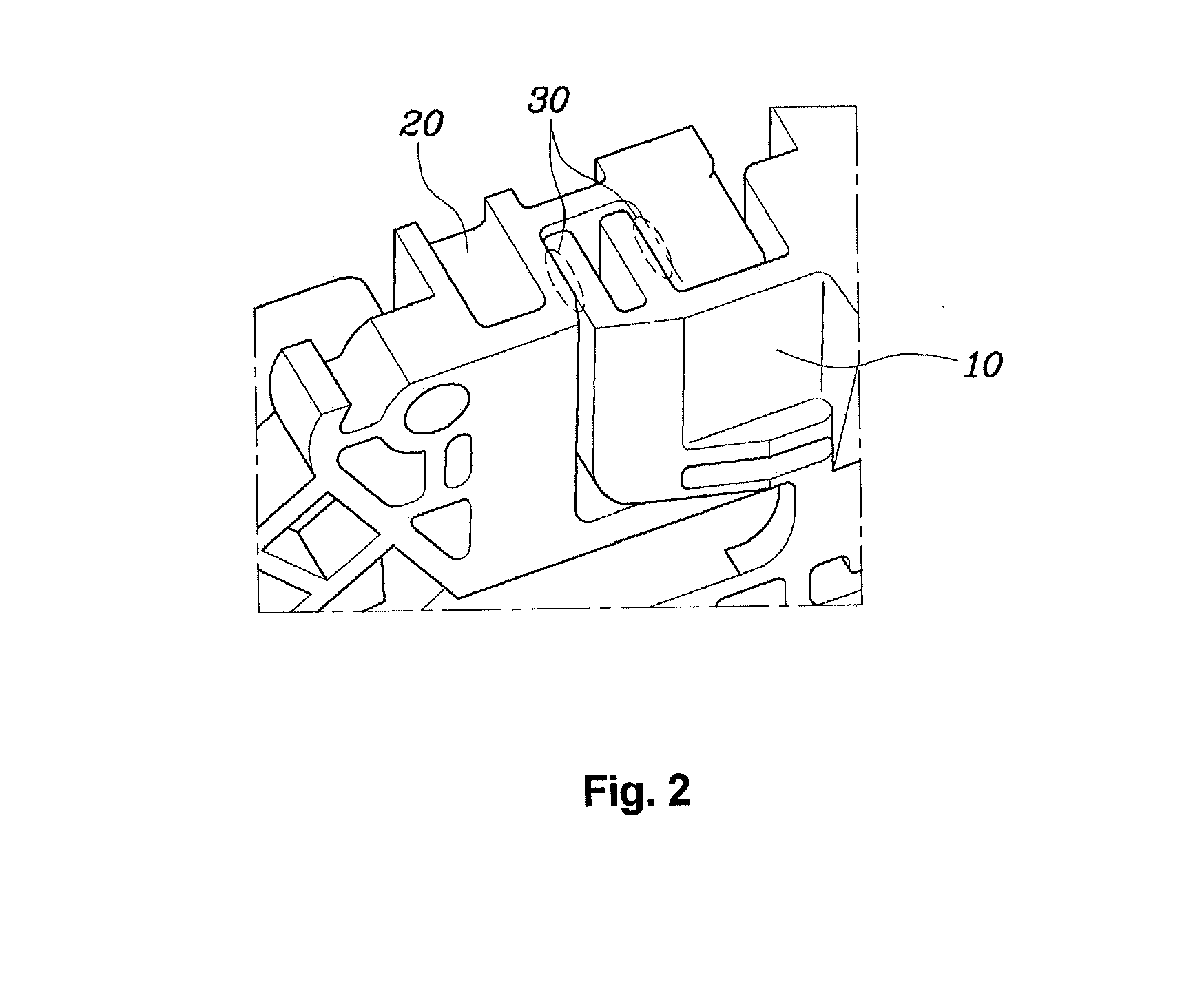
As shown in FIG. 2, the shift lever operation structure, however, has problems in that connection parts 30 between the shift plate 10 and the engaging plate that are connected with each other have an accumulated tolerance, thereby causing gaps or jams to occur.
On the contrary, if the connection parts 30 are made tight to remove the gaps, connection jams may occur at the connection parts.

Method used


Image

  • Shift lever operation structure
  • Shift lever operation structure
  • Shift lever operation structure

Examples


Embodiment Construction

[0027]Reference will now be made in detail to various embodiments of the present invention(s), examples of which are illustrated in the accompanying drawings and described below. While the invention(s) will be described in conjunction with exemplary embodiments, it will be understood that present description is not intended to limit the invention(s) to those exemplary embodiments. On the contrary, the invention(s) is / are intended to cover not only the exemplary embodiments, but also various alternatives, modifications, equivalents and other embodiments, which may be included within the spirit and scope of the invention as defined by the appended claims.

[0028]Wherever possible, the same reference numerals will be used throughout the drawings and the description to refer to the same or like parts.

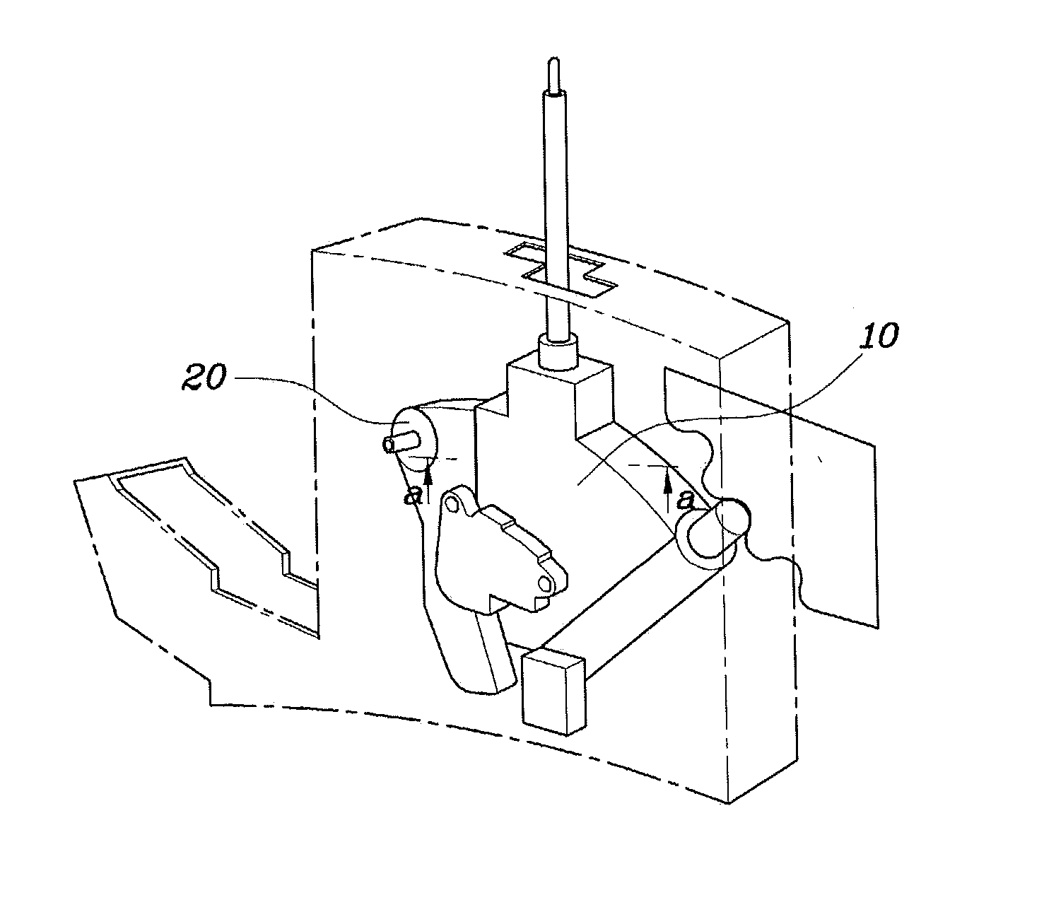
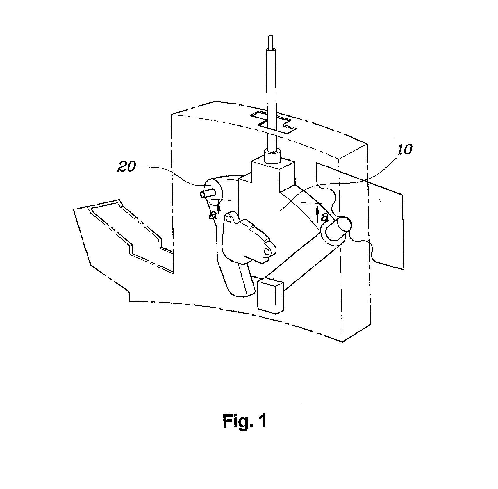
[0029]FIG. 3 is a perspective view of a shift lever operation structure according to various embodiments of the present invention. The shift lever operation structure includes: a shift plate ...


PUM


Abstract

A shift lever operation structure may include a shift plate, which moves along with a shift lever so that either manual or automatic mode is selected, and has an engaging part. An engaging plate may have a connection part corresponding to the engaging part so that, during the automatic mode, the engaging plate engages with the shift plate, and during the manual mode, the engaging plate is disengaged from the shift plate. An elastic member may be assembled with the connection part of the engaging plate such that the elastic member is deformed by the insertion of the engaging part into the connection part.

Description

CROSS REFERENCE TO RELATED APPLICATION[0001]The present application claims priority of Korean Patent Application Number 10-2012-0110925 filed Oct. 5, 2012, the entire contents of which application are incorporated herein for all purposes by this reference.BACKGROUND OF INVENTION[0002]1. Field of Invention[0003]The present invention relates, in general, to a shift lever operation structure capable of improving shift quality when a driver manipulates a shift lever.[0004]2. Description of Related Art[0005]Generally, among types of vehicle transmission there are a manual transmission, an automatic transmission, and a continuously variable transmission, and such devices operate according to changes in speed, and can convert torque and revolutions of an engine when a vehicle is driven.[0006]The transmission can change speed when a driver manipulates a shift lever so that an automatic mode or a manual mode is selected, thereby improving driving quality and providing convenience to the driv...

Claims


Application Information

Patent Timeline
Patent Type & Authority Applications(United States)
IPC IPC(8): F16H59/08
CPCF16H59/08F16H59/0204F16H59/10Y10T74/20177B60K20/02F16H59/02
Inventor CHOI, JEE HYUCKKIM, EUN SIKMIN, JEONG SEONYANG, HEE SOOCHO, YANG RAEYOUN, SUG JUNJANG, HO SIK
Owner HYUNDAI MOTOR CO LTD
Learn More