
Interactive user selected video/audio views by real time stitching and selective delivery of multiple video/audio sources

a real-time stitching and user-selected technology, applied in the field of interactive user-selected video/audio views by real-time stitching and selective delivery of multiple video/audio sources, can solve the problems of inability to quickly change to the desired view, mechanical system of moving camera, and inability to continuously view the scene in the area of different camera views

Inactive Publication Date: 2014-04-10
DAVARI SHAHRAM +1
View PDF17 Cites 78 Cited by
  • Summary
  • Abstract
  • Description
  • Claims
  • Application Information

AI Technical Summary

Benefits of technology

The patent describes a way to create a 360-degree view of a scene by combining multiple cameras. The cameras transmit their footage to a computing center, which stitches it and produces a complete view. This allows remote viewers to move their own viewing field and watch any part of the scene they desire. The effect is a more realistic viewing experience.

Problems solved by technology

In some other cases such as surveillance, the operator may be able to watch any of the cameras A / V stream by switching from one camera to another, but the operator cannot have a continuous view the scene in the areas where the views of different cameras overlap.
However there are drawbacks to this method.
First, a moving camera is a mechanical system and therefore prone to failure.
Second, rotating camera is due to its mechanical nature, and generally it is not possible to quickly change to a desired view.
Third, a rotating camera creates a limitation where there will be only a single common view for all audiences / viewers and in cases where multiple users each requires to have his / her own dedicated view, the overhead of having dedicated camera(s) for each user will be high.

Method used


Image

  • Interactive user selected video/audio views by real time stitching and selective delivery of multiple video/audio sources
  • Interactive user selected video/audio views by real time stitching and selective delivery of multiple video/audio sources
  • Interactive user selected video/audio views by real time stitching and selective delivery of multiple video/audio sources

Examples


Embodiment Construction

Functional Model

[0021]There are many functional elements that have to work together to create the desire user experience, who is viewing a live event remotely, while being able to watch any part of the event space at any time.

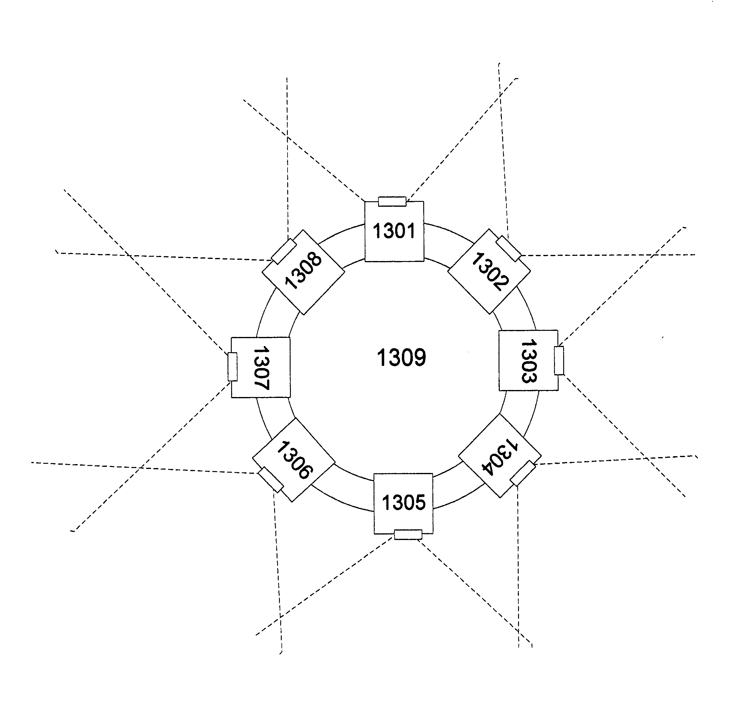
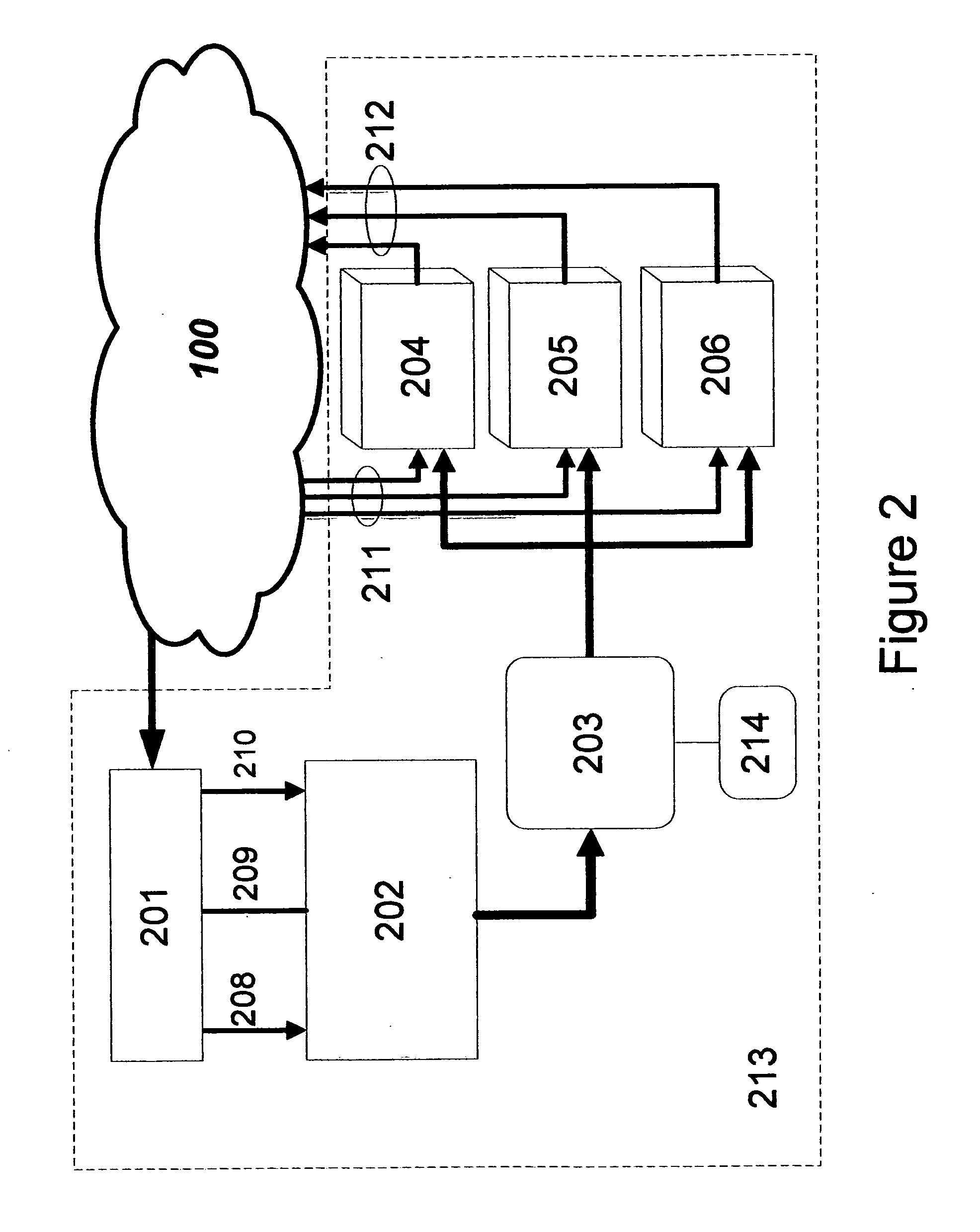
[0022]In one embodiment, the functional model comprises of 3 major functions:[0023]1. Event site functions (FIG. 1)[0024]2. Data center functions (FIG. 2)[0025]3. User site functions (FIG. 3)

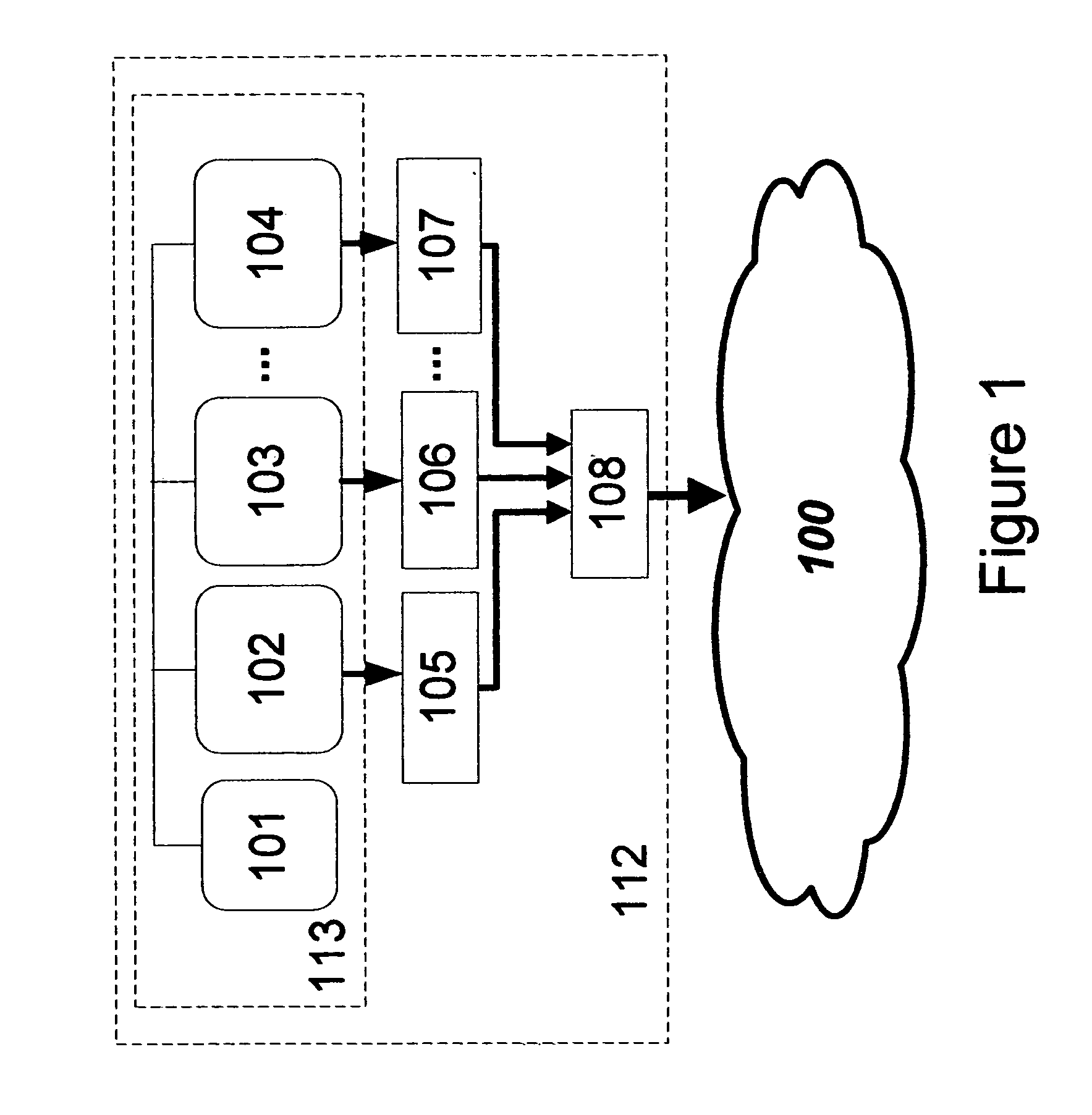
[0026]FIG. 1 shows one example of the Event site (112) along with its detail functional elements. In this example, there are a number of cameras (102, 103 . . . 104) that record the live event and generate AUDIO / VIDEO streams. These cameras are optionally synchronized to each other via a Sync line (101), in such a way that their frames are synchronized in time domain. The AUDIO / VIDEO output of each camera is optionally encoded and compressed (105, 106 . . . 107) and the result is then multiplexed via a Multiplexing function (108) and the result is then forwarded to the Data...


PUM


Abstract

This invention describes how a panoramic view can be created in real-time using multiple ordinary video cameras by splicing the video frames in real-time. It also describes how a subset of that panoramic view can be viewed on customer screen and how a customer can smoothly shift and scroll or zoom the customer view in real-time to view the other parts of the panoramic view using a remote control device. This invention also describes how all this can be achieved economically by using a cloud service such as assigning a Virtual Machine to each customer and using hardware acceleration engines in the data center such as high-end video cards.

Description

BACKGROUND OF THE INVENTION[0001]During live events, such as live sports events, live concerts, live news reports, surveillance, etc. usually there are multiple Cameras that capture, transmit and record Audio / Video (A / V) streams. However at any point in time only one of the A / V streams associated with just one of the cameras can be viewed by an audience (end user). In some cases such as sports events, concerts and live reports the audience has no control over which camera to watch, since the TV director decides which camera is broadcasted at any point in time to remote audience. In some other cases such as surveillance, the operator may be able to watch any of the cameras A / V stream by switching from one camera to another, but the operator cannot have a continuous view the scene in the areas where the views of different cameras overlap.[0002]One obvious and commonly deployed solution is to use cameras that can rotate across one or more axis. The audience or camera man can rotate the...

Claims


Application Information

Patent Timeline
IPC IPC(8): H04N7/00
CPCH04N7/00H04N7/002H04N23/698
Inventor DAVARI, SHAHRAMSALEMI, BEHNAM
Owner DAVARI SHAHRAM
Learn More