
Wide dynamic range display

a dynamic range and display technology, applied in the field of image display, can solve the problems of loss of local contrast, image details being lost when displayed, and appearing to be over-exposed in well-lit scenes or under-exposed in dark scenes

Inactive Publication Date: 2014-04-03
UTI LLP
View PDF13 Cites 8 Cited by
  • Summary
  • Abstract
  • Description
  • Claims
  • Application Information

AI Technical Summary

Benefits of technology

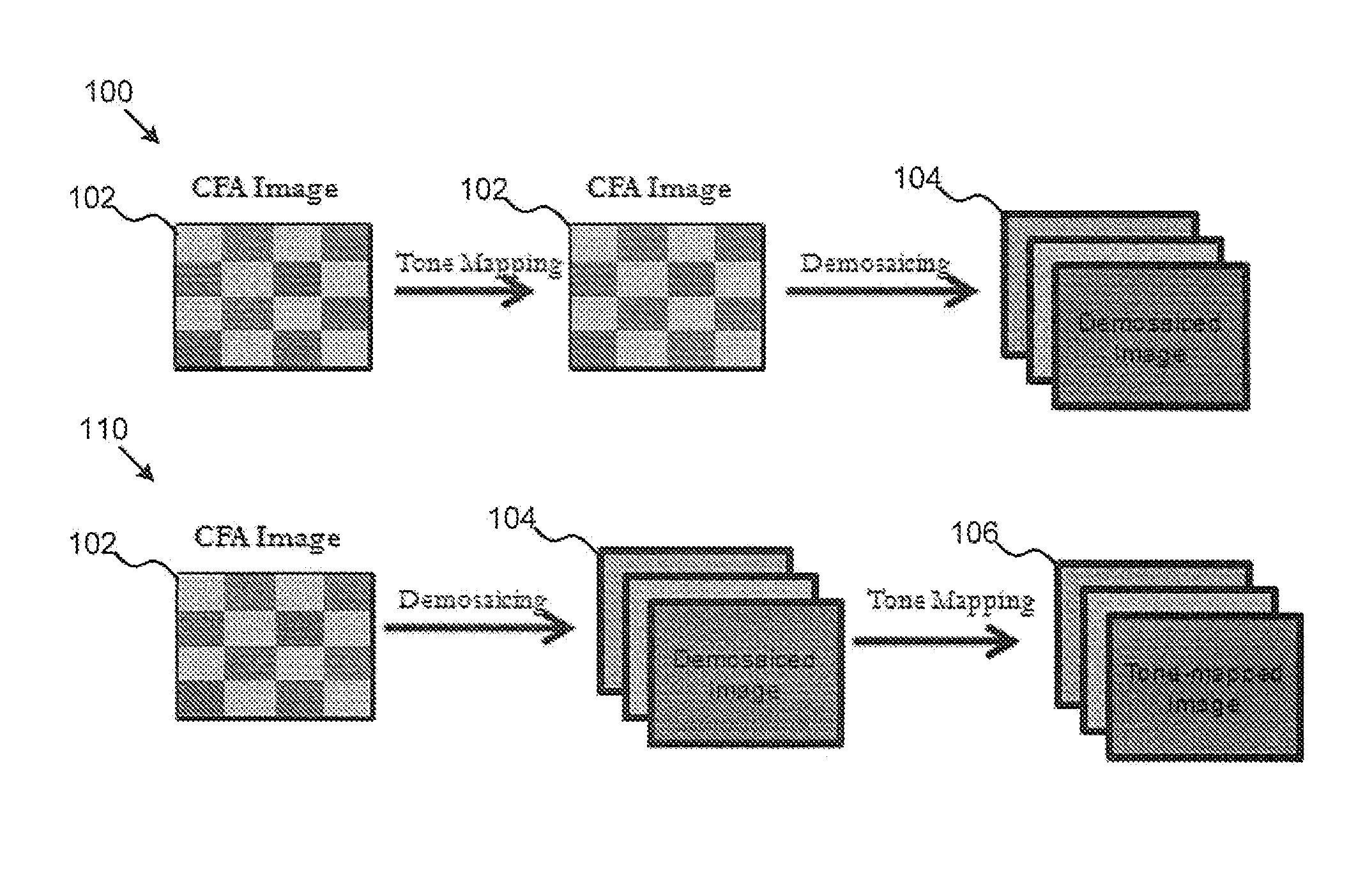
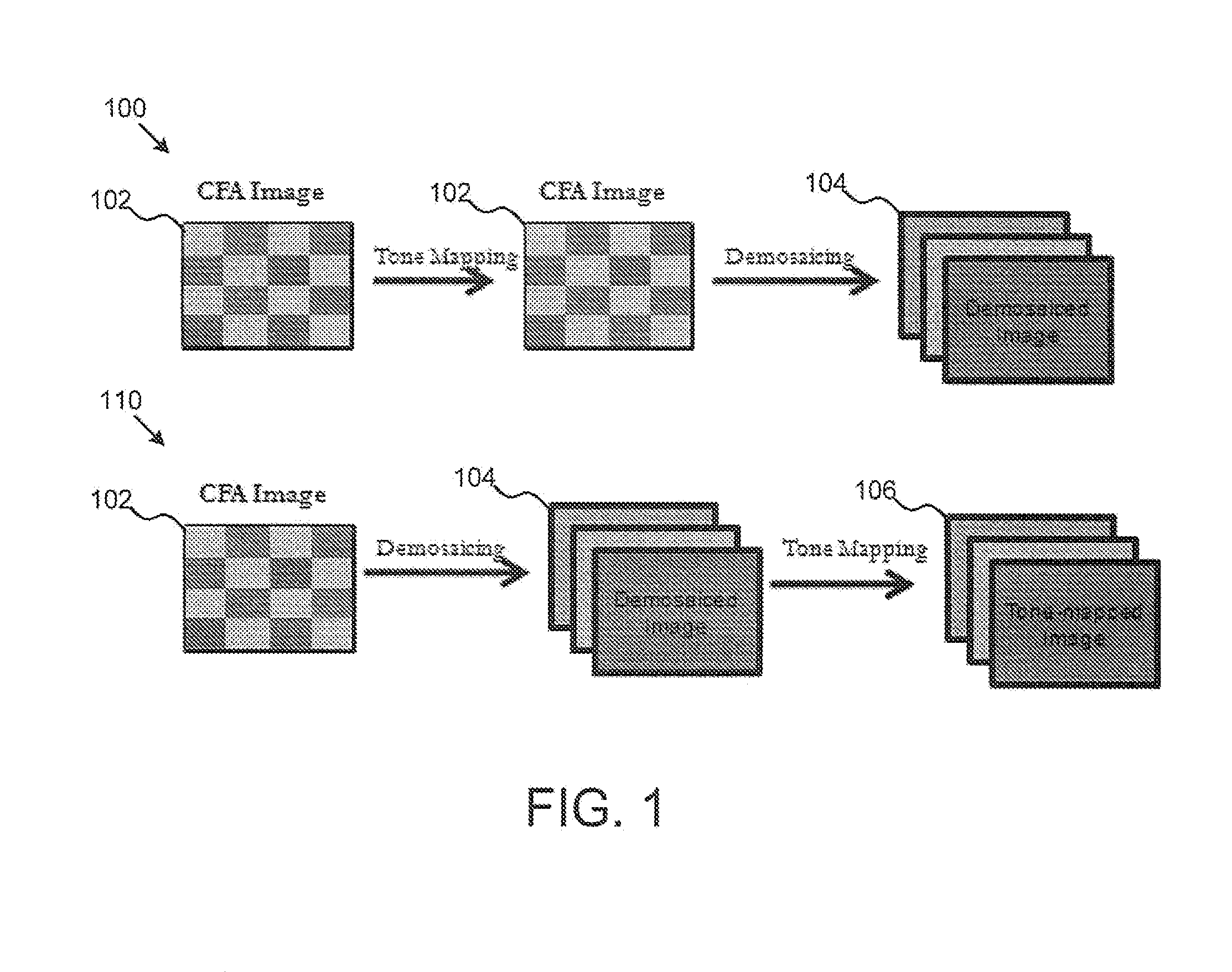
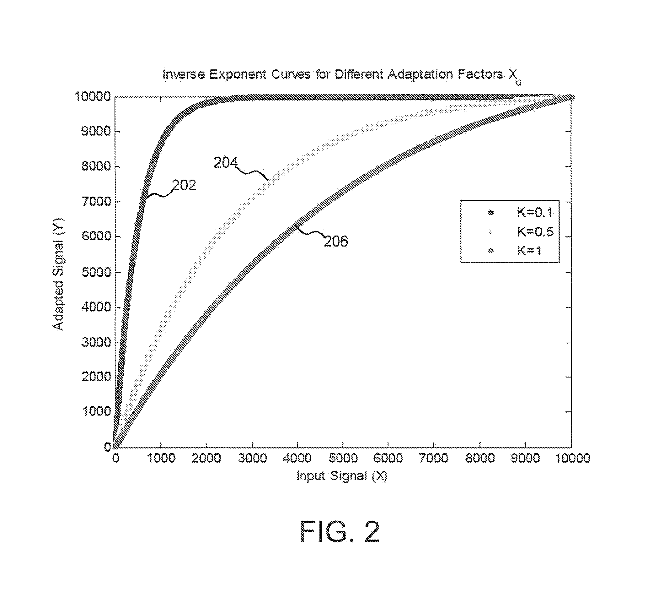
The patent describes methods and systems for displaying wide dynamic range (WDR) images using a color filter array (CFA) pixel signal. The CFA pixel signal is computed using an adaptation factor that has a global factor component and a local factor component. The adapted pixel signal is then convolved with a low-pass filter to produce an adapted pixel signal. The global factor component is determined based on two image key values, while the local factor component is determined based on the input light intensity at each pixel. The adapted signal has a value between 0 and 1 and is used to compute the image mean and maximum values for the CFA pixel data. The WDR image data is then tone- mapped using the image mean and maximum values to produce a final display. The technical effects of the patent include improved dynamic range and improved color accuracy in WDR images.

Problems solved by technology

However, when these captured wide dynamic range images are displayed on commonly used devices, they appear to be over-exposed in well-lit scenes or under-exposed in dark scenes.
Hence, image details will be lost when displayed.
TRC algorithms are generally less time consuming and require less computational effort but result in a loss of local contrast due to the global compression of the dynamic range.
In general, while TRO algorithms do not result in a loss of local contrast, they require more computational effort and may introduce artifacts such as halos to the resulting compressed image.
Consequently, TROs are less suitable for hardware implementation in comparison to TRC-based algorithms.

Method used


Image

  • Wide dynamic range display
  • Wide dynamic range display
  • Wide dynamic range display

Examples


Embodiment Construction

[0042]Various features and advantageous details are explained more fully with reference to the nonlimiting embodiments that are illustrated in the accompanying drawings and detailed in the following description. Descriptions of well known starting materials, processing techniques, components, and equipment are omitted so as not to unnecessarily obscure the invention in detail. It should be understood, however, that the detailed description and the specific examples, while indicating embodiments of the invention, are given by way of illustration only, and not by way of limitation. Various substitutions, modifications, additions, and / or rearrangements within the spirit and / or scope of the underlying inventive concept will become apparent to those skilled in the art from this disclosure.

[0043]Embodiments of a pipelined tone mapping hardware architecture for WDR images based on an exponent-based algorithm are described. The algorithm comprises of a global and a local tone mapping operat...


PUM


Abstract

Methods and systems for wide dynamic range display are presented. In one embodiment, a method includes receiving a Color Filter Array (CFA) pixel signal, computing, using image processing hardware, an adaptation factor for the CFA pixel signal, the adaptation factor having a global factor component and a local factor component, and computing, using the image processing hardware, an adapted pixel signal for the CFA pixel in response to a reverse exponential function featuring the adaptation factor. In one embodiment, computing the adapted pixel signal for the CFA pixel does not require frame memory. Also, the adaptation factor may have a value between 0 and 1, in certain embodiments.

Description

CROSS-REFERENCE TO RELATED APPLICATIONS[0001]This application claims the benefit of U.S. Provisional Patent Application No. 61 / 661,117 filed on Jun. 18, 2012, the entire contents of which is specifically incorporated herein by reference without disclaimer.BACKGROUND OF THE INVENTION[0002]1. Field of the Invention[0003]This invention relates to image display and more particularly relates to an apparatus system and method for wide dynamic range display.[0004]2. Description of the Related Art[0005]In imaging, dynamic range can be described as the luminance ratio between the brightest and darkest parts of a scene. Natural sceneries have a wide dynamic range that can exceed 100,000,000:1, while commonly used display devices have a limited dynamic range which is generally less than 1000:1.[0006]Emerging image capture devices can produce wide dynamic range images, which have a higher dynamic range in comparison to the commonly used display devices. However, when these captured wide dynamic...

Claims


Application Information

Patent Timeline
IPC IPC(8): G06T11/00
CPCG06T11/001G06T3/4015
Inventor OFILI, CHIKA ANTOINETTEGLOZMAN, STANISLAVYADID-PECHT, ORLYHORE, ALAIN
Owner UTI LLP
Learn More