
Laminate

a technology of laminate and film type elements, applied in the field of laminate, can solve the problems of reducing the drive efficiency of the piezoelectric/electrostrictive film type elemen

Inactive Publication Date: 2014-04-03
NGK INSULATORS LTD
View PDF4 Cites 7 Cited by
  • Summary
  • Abstract
  • Description
  • Claims
  • Application Information

AI Technical Summary

Benefits of technology

The patent text discusses a problem with traditional piezoelectric / electrostrictive film type elements, which have a trapezoid sectional shape that causes a reduction in the distance between the upper and lower ends of the piezoelectric layer, leading to leak current and decreased drive efficiency. The inventors found that using a "substantially rectangular shape" for the piezoelectric layer sectional shape can improve drive efficiency, but may also result in leak current. To solve this problem, the patent proposes a laminate with a dielectric layer having a surface roughness of 0.05 dμm or more and 0.5 dμm or less at the maximum height roughness Rz. This laminate prevents both leak current and particle shedding, ensuring improved performance of the piezoelectric / electrostrictive film type element.

Problems solved by technology

This fact leads to reduction in drive efficiency of the piezoelectric / electrostrictive film type element.
As a result, when a voltage is applied between the upper and lower electrodes, a leak current that flows through the piezoelectric layer is easily generated.
When a large amount of leak current flows, there may arise problems in that the drive efficiency of the piezoelectric / electrostrictive film type element decreases, etc.

Method used


Image

  • Laminate
  • Laminate
  • Laminate

Examples


Embodiment Construction

[0026](Configuration)

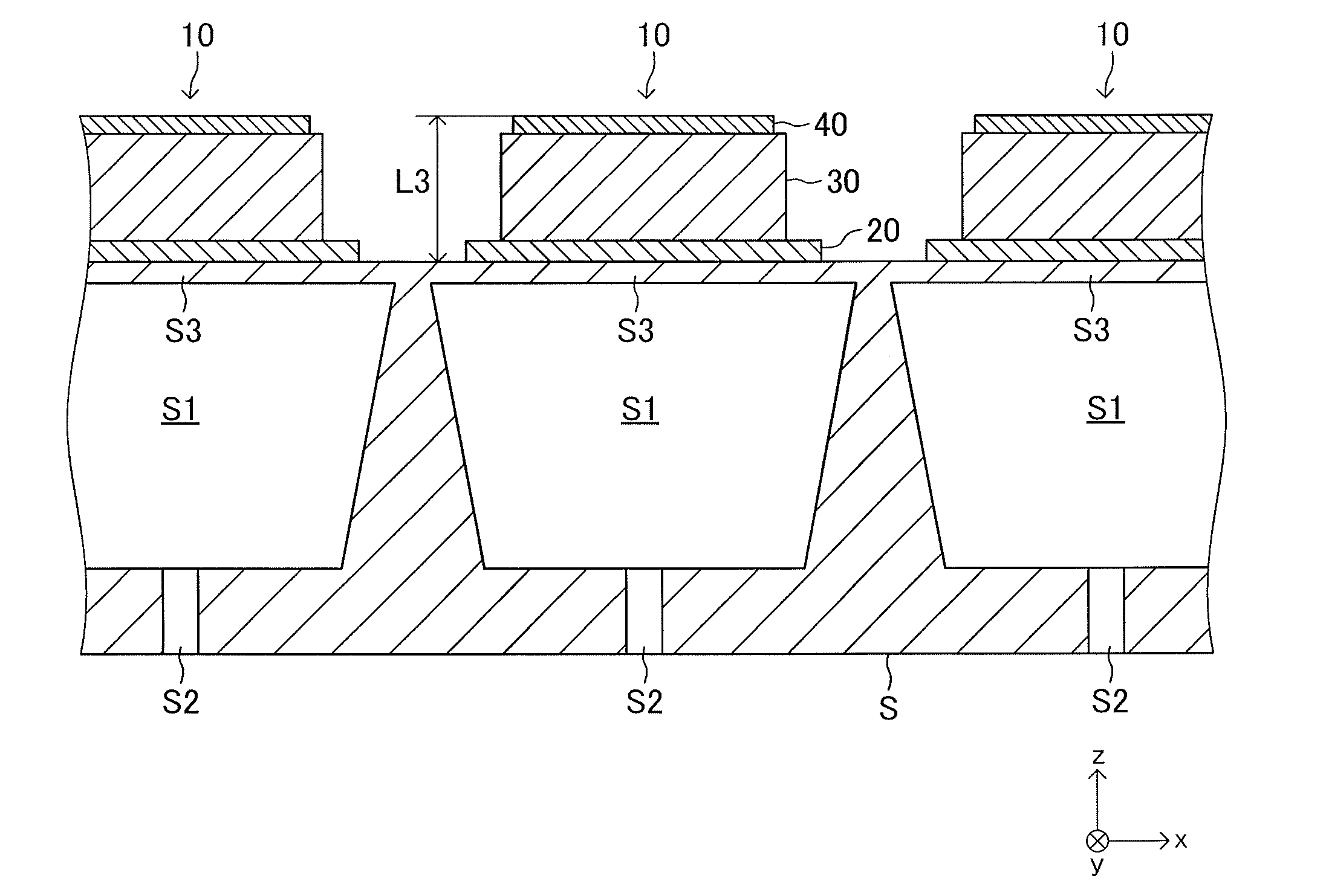
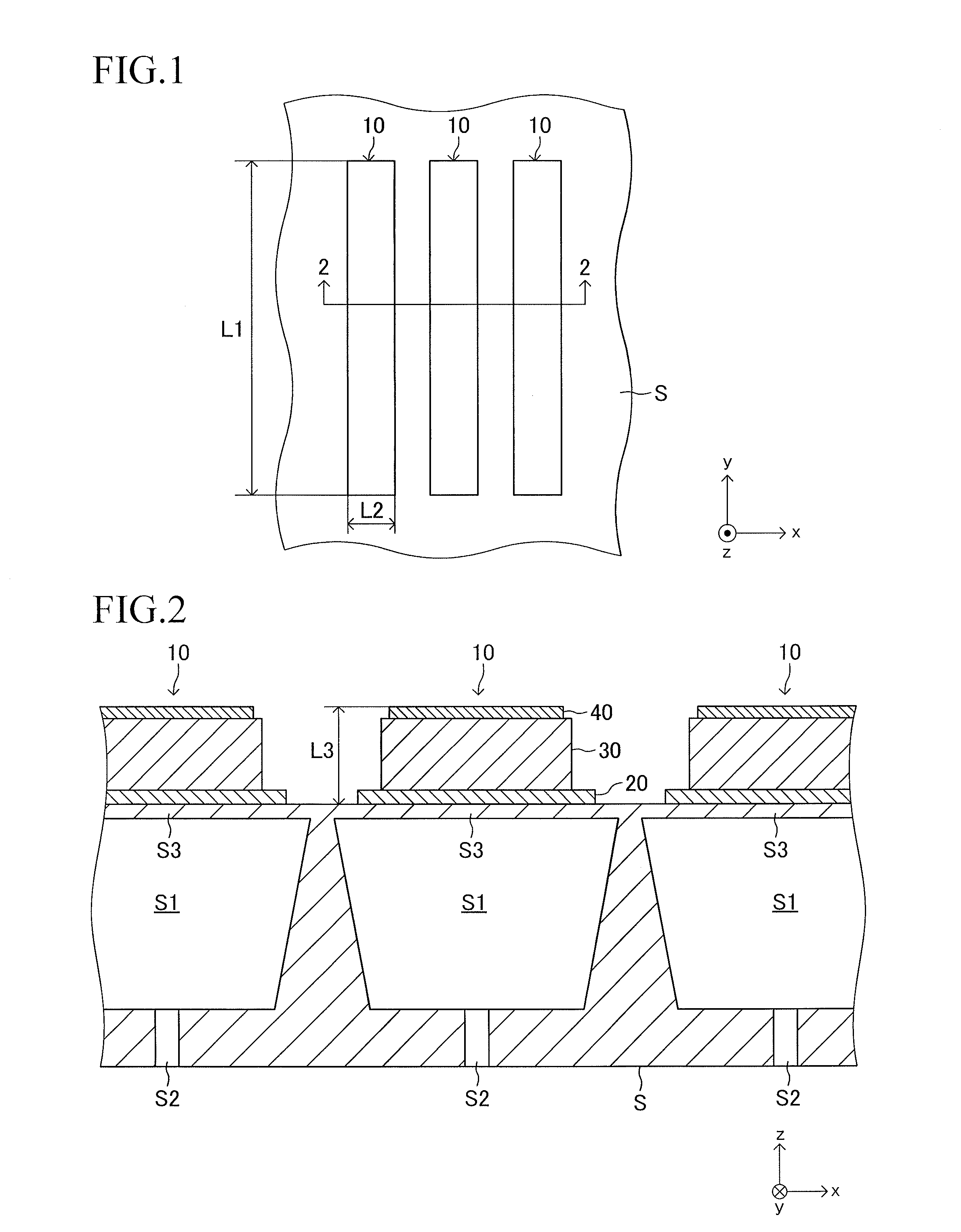
[0027]Now, the configuration of a piezoelectric / electrostrictive film type element according to an embodiment of the present invention is described with reference to the drawings. As illustrated in FIGS. 1 and 2, piezoelectric / electrostrictive film type elements 10 according to the embodiment of the present invention are formed on an upper surface of a support S at a plurality of positions so as to be arrayed at predetermined intervals. Each of the piezoelectric / electrostrictive film type elements 10 is used as a drive source of an ink jet head of an ink jet printer.

[0028]As illustrated in FIG. 1, when viewed from above (z-axis positive direction), each of the piezoelectric / electrostrictive film type elements 10 has a planar shape that is a rectangle having a longitudinal direction (y-axis direction). FIG. 2 illustrates a cross-section of the piezoelectric / electrostrictive film type elements 10 taken along a thickness direction (z-axis direction) and a “directio...


PUM


Abstract

A piezoelectric / electrostrictive film type element includes a lower electrode, a piezoelectric layer, and an upper electrode laminated in order on a support. An average particle diameter of each of particles of a piezoelectric material forming the piezoelectric layer falls within a range of 0.5 μm to 10 μm. The sectional shape of the piezoelectric layer is a “quadrilateral (substantially rectangular shape) having a height of from 0.5 μm to 15 μm and an angle (θ) at an end point of a base of from 85° to 105°.” A surface roughness of a side surface of the piezoelectric layer is 0.05 dμm to 0.5 dμm at the maximum height roughness Rz (defined by JIS B 0601:2001). Both “generation of a leak current that flows through the piezoelectric layer” and “occurrence of particle shedding from a side surface of the piezoelectric layer” can be prevented.

Description

BACKGROUND OF THE INVENTION[0001]1. Field of the Invention[0002]The present invention relates to a “laminate including a lower electrode, a dielectric layer, and an upper electrode,” which is formed on a support, and more particularly, to a laminate that includes a piezoelectric layer as a dielectric layer and functions as a piezoelectric / electrostrictive film type element.[0003]2. Description of the Related Art[0004]Hitherto, there has been widely known a piezoelectric / electrostrictive film type element that is a laminate including a plate-like lower electrode formed on a support, a piezoelectric layer that is a fired body formed on the lower electrode, and a plate-like upper electrode formed on the piezoelectric layer so as to be opposed in parallel to the lower electrode (see, for example, Japanese Patent Application Laid-open No. 2010-219153). Such a piezoelectric / electrostrictive film type element is widely used as, for example, a drive source of an ink jet head (part for eject...

Claims


Application Information

Patent Timeline
Patent Type & Authority Applications(United States)
IPC IPC(8): H01L41/08
CPCH01L41/0805B41J2/161B41J2/1626B41J2/1631B41J2/1643B41J2/1645B41J2/1646H10N30/2047H10N30/082H10N30/704
Inventor KOIZUMI, TAKAAKIEBIGASE, TAKASHITAKEMURA, SHINYA
Owner NGK INSULATORS LTD
Learn More