Display device
a display device and display screen technology, applied in the field of display devices, can solve the problems of narrowed vertical angular range, increased difficulty in adjusting brightness, and discomfort of people,
- Summary
- Abstract
- Description
- Claims
- Application Information
AI Technical Summary
Benefits of technology
Problems solved by technology
Method used
Image
Examples
first preferred embodiment
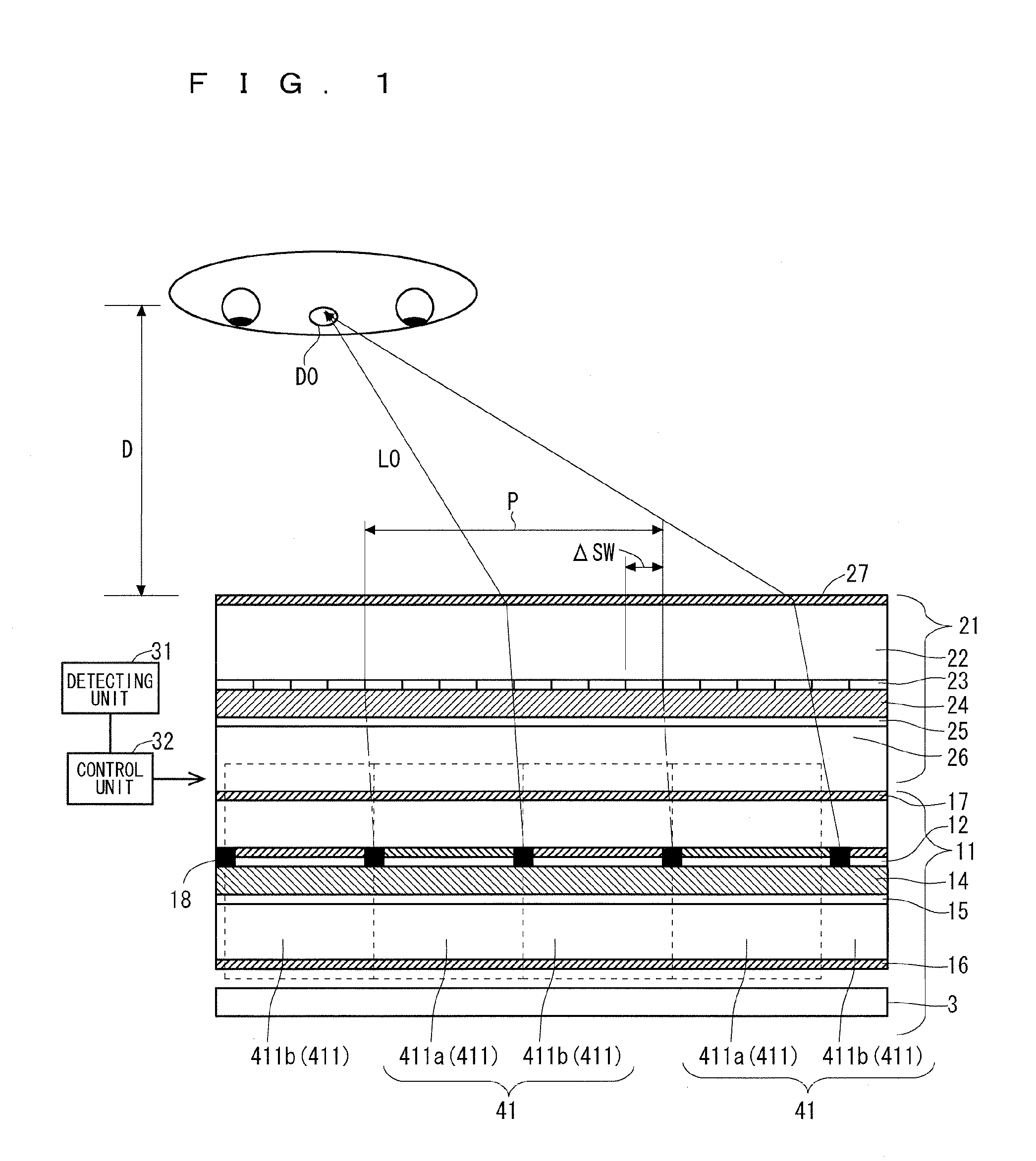
[0040]FIG. 1 is a sectional view illustrating a configuration of a display device according to a first preferred embodiment of the present invention. The display device can simultaneously display two images, which are a right image (a parallax image for right eye, or an image for a first observation direction) and a left image (a parallax image for left eye that is slightly different from the parallax image for the right eye, or an image for a second observation direction). With this display device, a user can visually confirm a 3D image with the naked eye without using special glasses. Alternatively, the display device can display different images for each observation direction. The case where the display device displays a parallax image for the right eye and a parallax image for the left eye will mainly be described below.
[0041]This display device includes a glasses-free 3D display described later, a detecting unit 31 that detects a position (motion) of a head of an observer, and ...
second preferred embodiment
[0124]In the first preferred embodiment, the number of the first transparent electrodes 23 arranged in the longitudinal direction of the parallax barrier shutter panel 21 is N / 2 times the number of the wirings arranged in the longitudinal direction of the display panel 11. Specifically, the number of the first transparent electrodes is relatively large. In this structure, the drive of the segment system on the parallax barrier shutter panel 21 is difficult. The number of the joint points with a flexible circuit board for externally applying voltage increases, and the pitch of the joint portions becomes small, which makes the mounting work somewhat difficult. Alternatively, the number of the necessary driving ICs increases, which might increase the cost of the components.
[0125]A glasses-free 3D display (display device) according to the second preferred embodiment of the present invention can solve the problem described above. In the description of the glasses-free 3D display (display...
third preferred embodiment
[0162]FIG. 27 illustrates a cross-sectional structure of the parallax barrier shutter panel 21 on a glasses-free 3D display according to a third preferred embodiment. In the description of the display device according to the present preferred embodiment, the components same as or similar to those described in the first and second preferred embodiments are identified by the same numerals, and the different point will mainly be described.
[0163]When the parallax barrier shutter panel 21 is combined to the display panel, the parallax barrier shutter panel 21 may be provided close to the observer than to the display panel 11 (anteriorly to the display panel 11), or when the liquid crystal display panel is used for the display panel 11, the parallax barrier shutter panel 21 may be provided between the backlight and the display panel 11 (posteriorly to the display panel 11).
[0164]The parallax barrier shutter panel 21 according to the third preferred embodiment is configured to be almost th...
PUM
 Abstract
Description
Claims
Application Information
 - R&D
- Intellectual Property
- Life Sciences
- Materials
- Tech Scout
- Unparalleled Data Quality
- Higher Quality Content
- 60% Fewer Hallucinations
Browse by: Latest US Patents, China's latest patents, Technical Efficacy Thesaurus, Application Domain, Technology Topic, Popular Technical Reports.
© 2025 PatSnap. All rights reserved.Legal|Privacy policy|Modern Slavery Act Transparency Statement|Sitemap|About US| Contact US: help@patsnap.com


