
Electronic power steering apparatus

Active Publication Date: 2014-03-20
JTEKT CORP
View PDF5 Cites 10 Cited by
  • Summary
  • Abstract
  • Description
  • Claims
  • Application Information

AI Technical Summary

Benefits of technology

The present invention is an electronic power steering system that can detect when there is no normal signal from a torque sensor and efficiently prevent unintentional application of an assist force to the steering system. This system allows for easy setting of upper and lower limits for the assist control variable and ensures smooth steering operation without hindering the driver's ability to control the vehicle. The control means gradually decreases the assist force in the event of an abnormal sensor signal, which prevents sudden changes in the assist force and ensures safe driving.

Problems solved by technology

Thus, it is likely in conventional electronic power steering apparatuses that an assist force is applied to a steering system unintentionally during a period from detecting no normal sensor signal generated by plural systems and outputted from a torque sensor to suspending an assist force provided by a steering force assist device.

Method used


Image

  • Electronic power steering apparatus
  • Electronic power steering apparatus
  • Electronic power steering apparatus

Examples


first embodiment

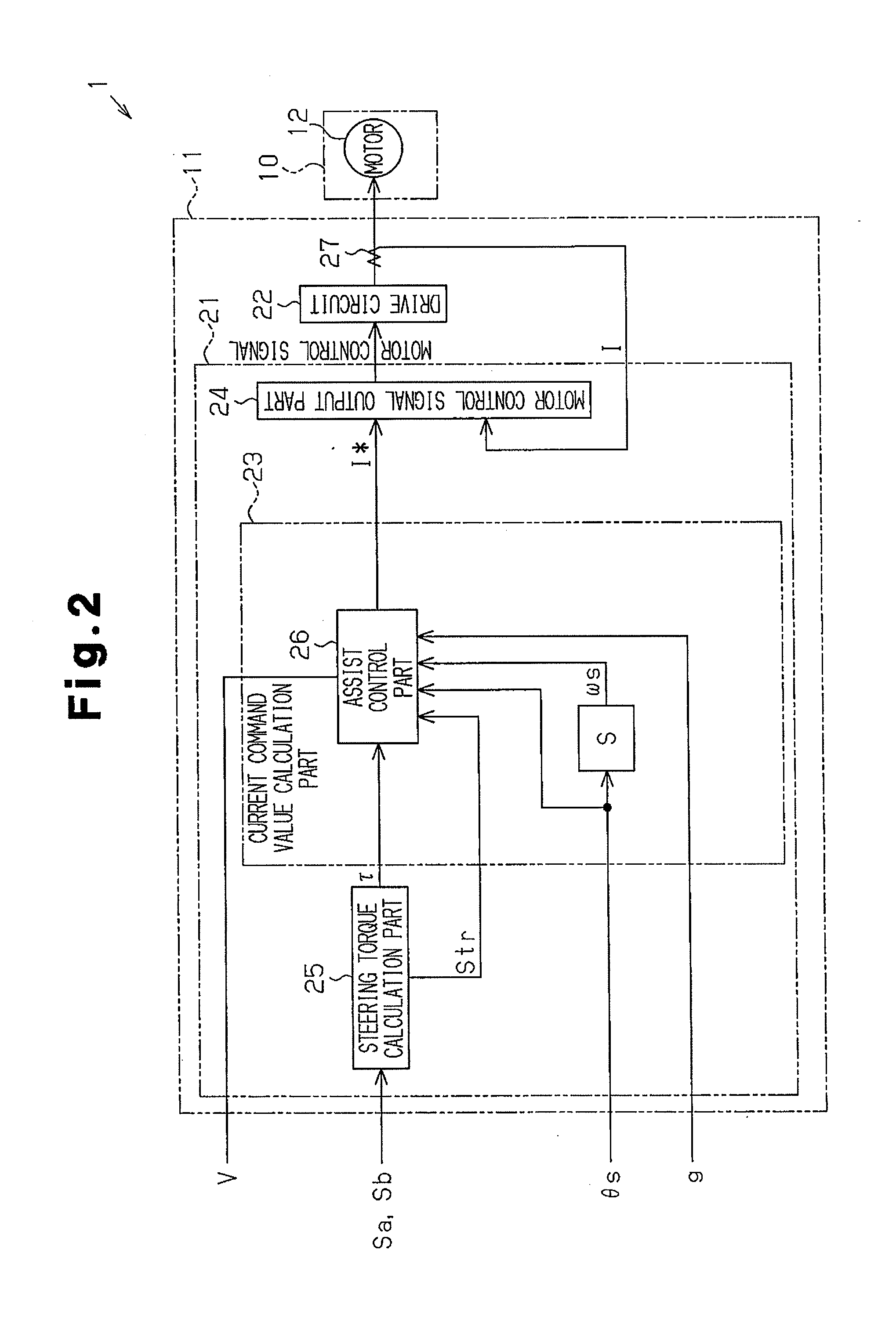
[0027]Explained below according to FIG. 1 to FIG. 5 is a first embodiment in which a concrete example of an electronic power steering apparatus (EPS) of the present invention is presented.

[0028]As shown in FIG. 1, a steering wheel 2 is continuously fixed to a steering shaft 3 and connected to a rack shaft 5 via a rack-and-pinion mechanism 4. When a driver operates the steering wheel 2, the steering shaft 3 rotates and rotation of the steering shaft 3 is converted into a linear reciprocating motion of the rack shaft 5 via the rack-and-pinion mechanism 4.

[0029]The steering shaft 3 is composed of a column shaft 3a, an intermediate shaft 3b and a pinion shaft 3c that are connected to each other. A torsion bar 17 is attached to a middle part of the column shaft 3a. Both ends of the rack shaft 5 are connected to tie rods 6. Linear motion of the rack shaft 5 is transmitted to knuckles not shown via the tie rods 6. The mechanism causes a change in the steering angle of steered wheels 7 so t...

second embodiment

[0064]Explained below with reference to FIG. 6 is a second embodiment in which a concrete example of the electronic power steering apparatus according to the present invention is presented. Note that detailed explanation of parts similar to the first embodiment is omitted in the second embodiment.

[0065]As shown in FIG. 6, an assist control part 126 includes the basic assist control variable calculation part 28 and a control variable restriction processing part 129. The control variable restriction processing part 129 receives, in addition to the basic assist control variable ε_as, the vehicle speed V detected by the vehicle speed sensor 15, the steering angle θs detected by the steering sensor 16, and the abnormality detection signal Str outputted from the steering torque calculation part 25. The control variable restriction processing part 129 executes an assist restriction process corresponding to the steering angle θs when only one of the sensor signals Sa and Sb is detected as a...


PUM


Abstract

When only one of sensor signals generated by the plural systems and output from a torque sensor is normal, a control variable restriction processing part performs an assist restricting process for setting an upper limit value and a lower limit value of a basic assist control variable in accordance with at least one of the lateral acceleration, the steering angle, the steering speed, or the yaw rate.

Description

TECHNICAL FIELD[0001]The present invention relates to an electronic power steering apparatus.BACKGROUND ART[0002]In general, electronic power steering apparatuses (EPS) are provided with a motor serving as a drive source and a torque sensor. The torque sensor outputs a sensor signal based on torsion of a torsion bar provided in the middle of a steering shaft. Then, in response to a steering torque detected based on a sensor signal sent from the torque sensor, a torque in the motor is controlled so that an appropriate assist force is applied to a steering system in accordance with a steering torque. It is therefore necessary in electronic power steering apparatuses to detect a steering torque in a stable and highly accurate manner so that an appropriate assist force can be obtained.[0003]For example, Patent Document 1 discloses a torque sensor for use in an electronic power steering apparatus for vehicle. The torque sensor disclosed in this document is provided with an input shaft, a...

Claims


Application Information

Patent Timeline
IPC IPC(8): B62D5/04
CPCB62D5/0463B62D5/0484B62D5/049
Inventor ITAMOTO, HIDENORIEKI, HIROZUMINAKASONE, GEMPEI
Owner JTEKT CORP
Learn More