Fixed constant velocity universal joint
- Summary
- Abstract
- Description
- Claims
- Application Information
AI Technical Summary
Benefits of technology
Problems solved by technology
Method used
Image
Examples
Embodiment Construction
[0053]Description is made of embodiments of the present invention with reference to FIGS. 1 to 11.
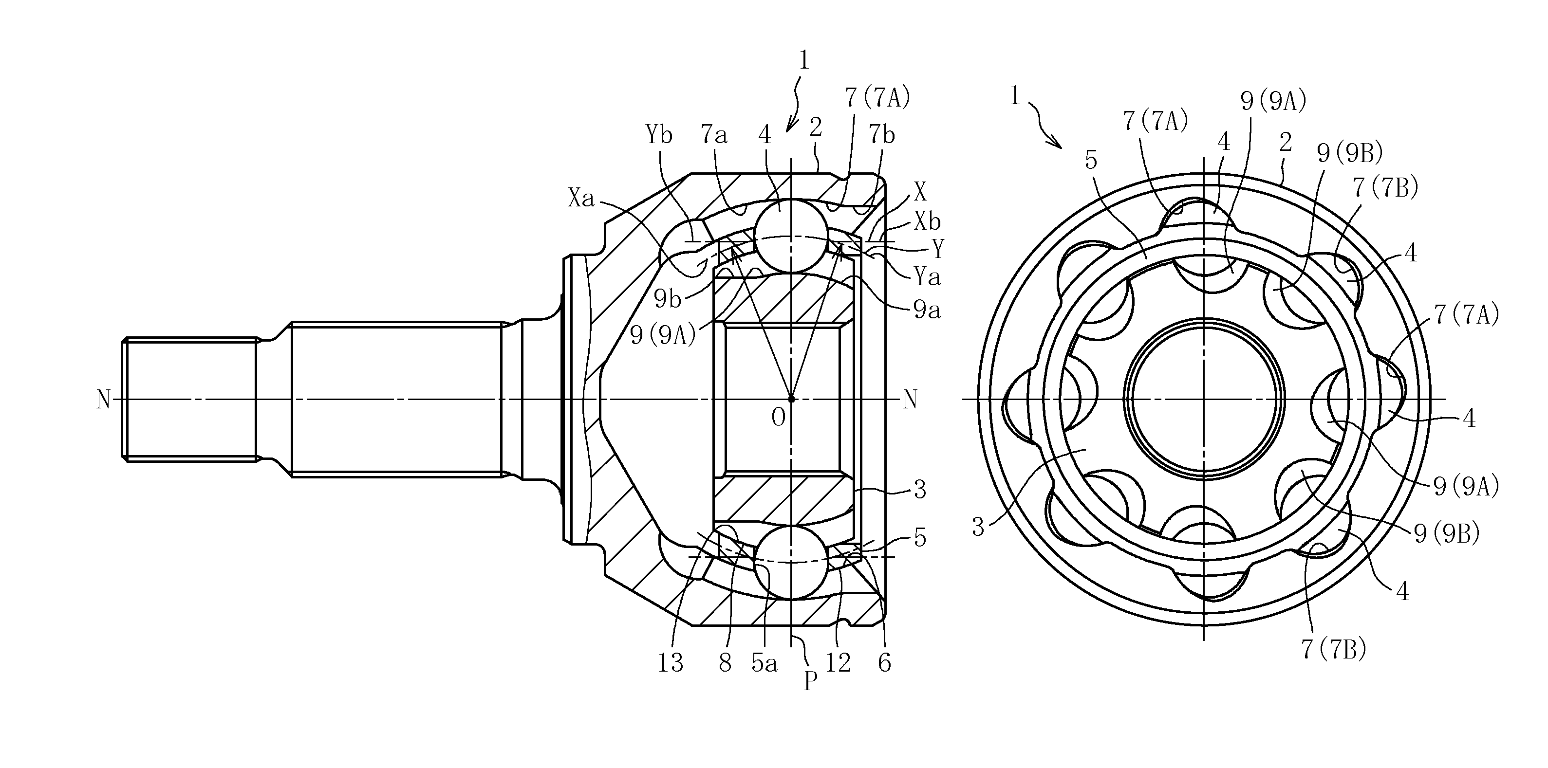
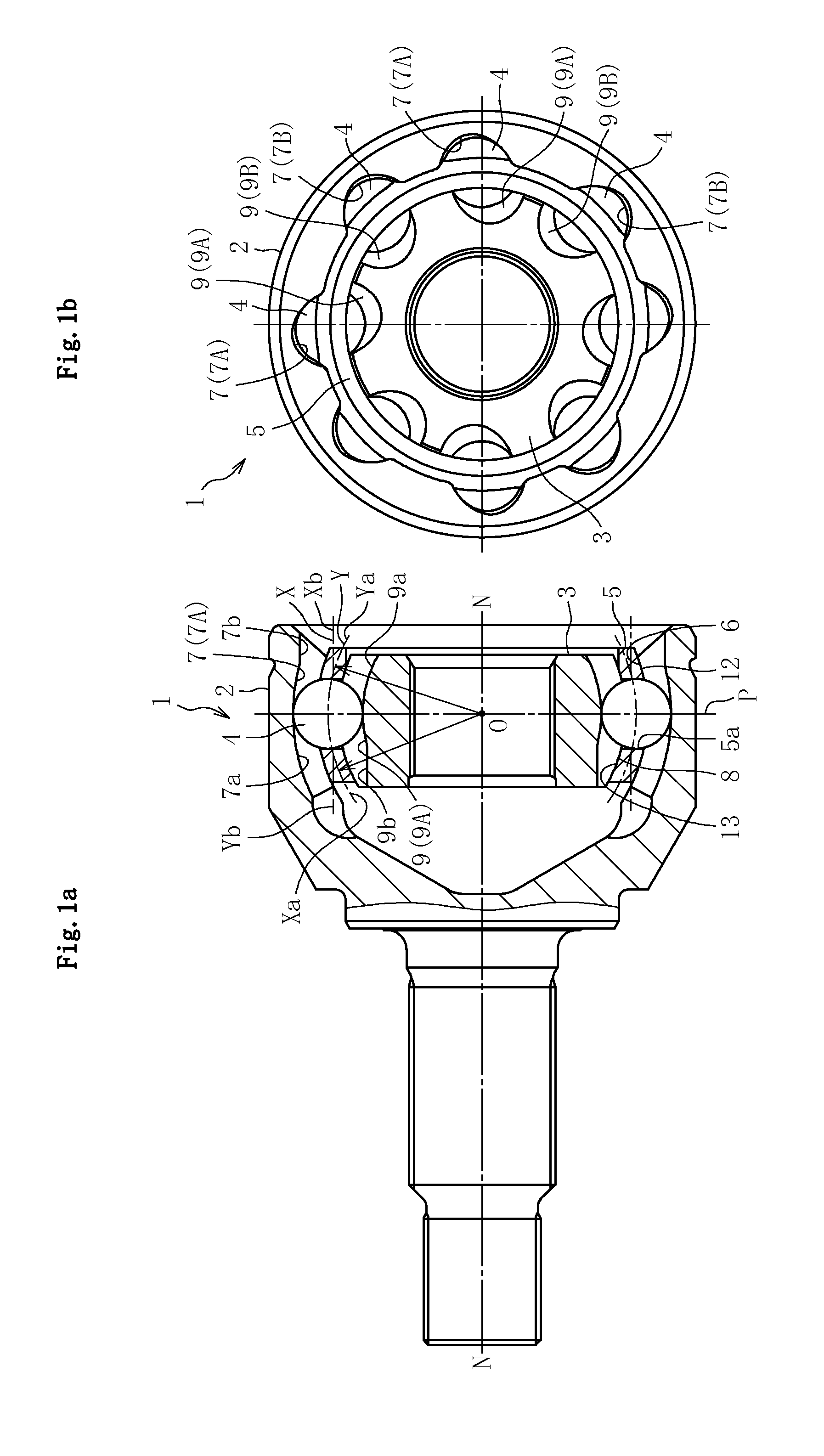
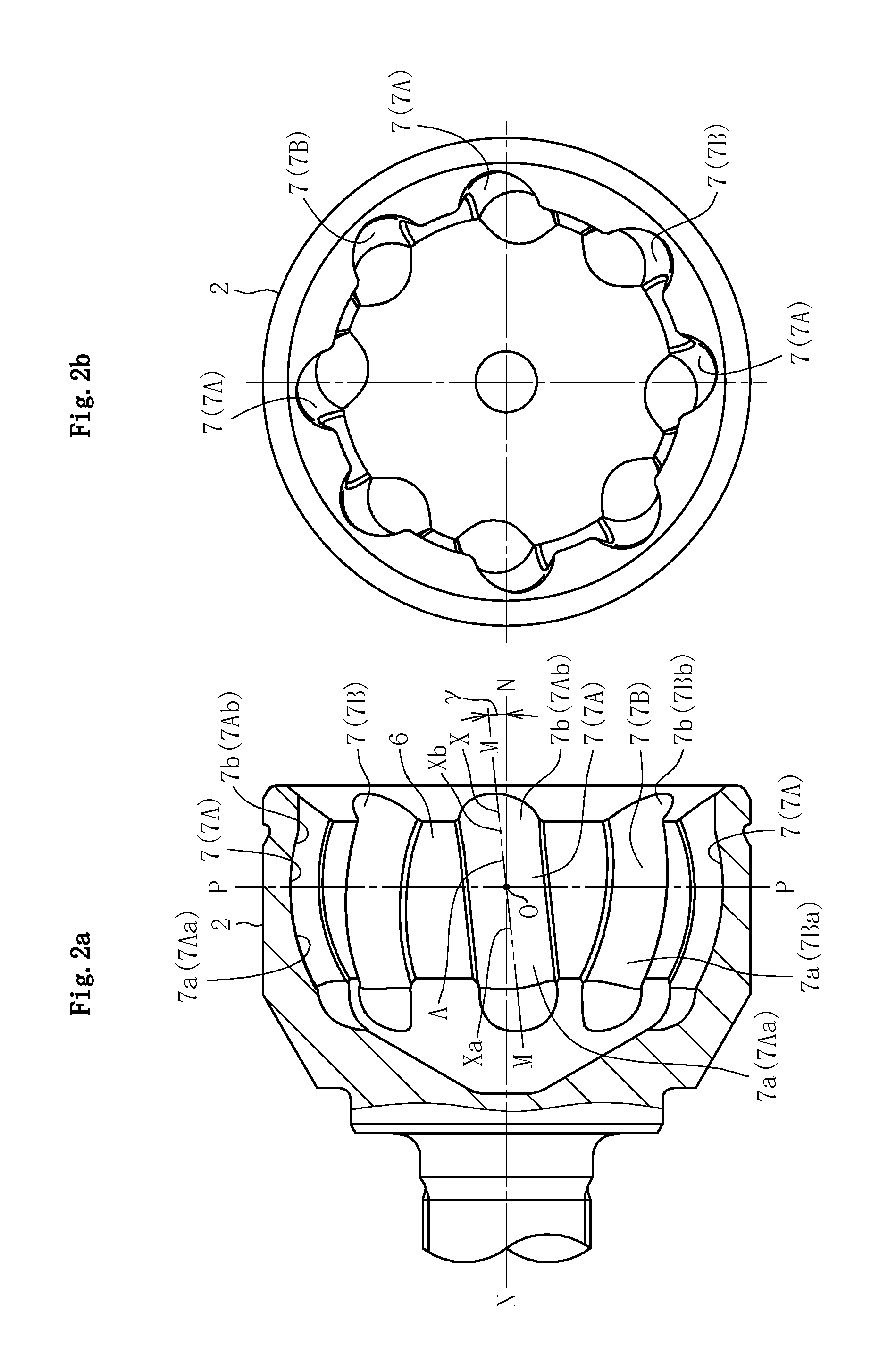
[0054]FIGS. 1 to 8 illustrate a first embodiment of the present invention. FIG. 1 illustrate a fixed type constant velocity universal joint according to the first embodiment. FIG. 1a is a partial vertical sectional view, and FIG. 1b is a right side view of FIG. 1a. A constant velocity universal joint 1 of this embodiment comprises, as main components, an outer joint member 2, an inner joint member 3, balls 4, and a cage 5. As illustrated in FIG. 1b, FIG. 2, and FIG. 3, eight track grooves 7 and 9 of the outer joint member 2 and the inner joint member 3 respectively comprise track grooves 7A and 7B and track grooves 9A and 9B that are inclined in a circumferential direction with respect to a joint axial line N-N and respectively adjacent to each other in the circumferential direction with their inclination directions opposite to each other. Further, the eight balls 4 are arranged in inte...
PUM
 Abstract
Description
Claims
Application Information
 - R&D
- Intellectual Property
- Life Sciences
- Materials
- Tech Scout
- Unparalleled Data Quality
- Higher Quality Content
- 60% Fewer Hallucinations
Browse by: Latest US Patents, China's latest patents, Technical Efficacy Thesaurus, Application Domain, Technology Topic, Popular Technical Reports.
© 2025 PatSnap. All rights reserved.Legal|Privacy policy|Modern Slavery Act Transparency Statement|Sitemap|About US| Contact US: help@patsnap.com


