Fixed constant velocity universal joint
a constant velocity, universal joint technology, applied in the direction of yielding couplings, couplings, mechanical devices, etc., can solve the problems of restricting a further increase in efficiency and suppression of heat generation, and achieves high operating angles, reduce torque loss and heat generation, and reduce the effect of aging
- Summary
- Abstract
- Description
- Claims
- Application Information
AI Technical Summary
Benefits of technology
Problems solved by technology
Method used
Image
Examples
first embodiment
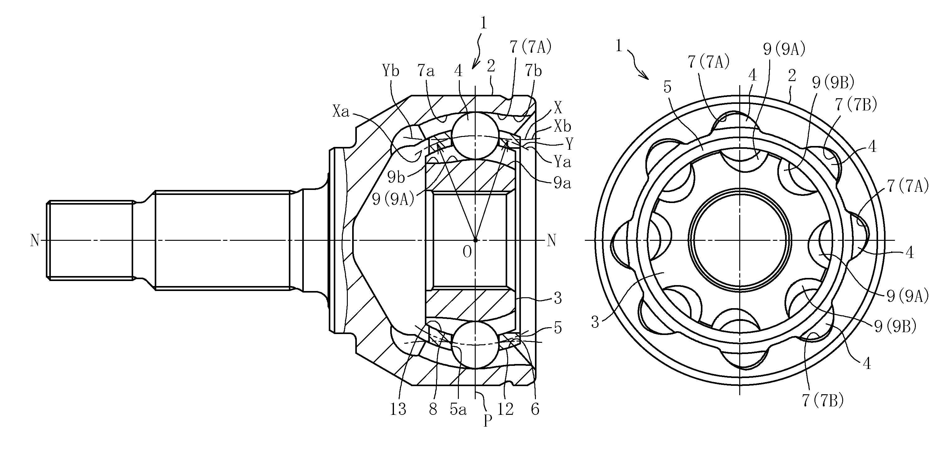
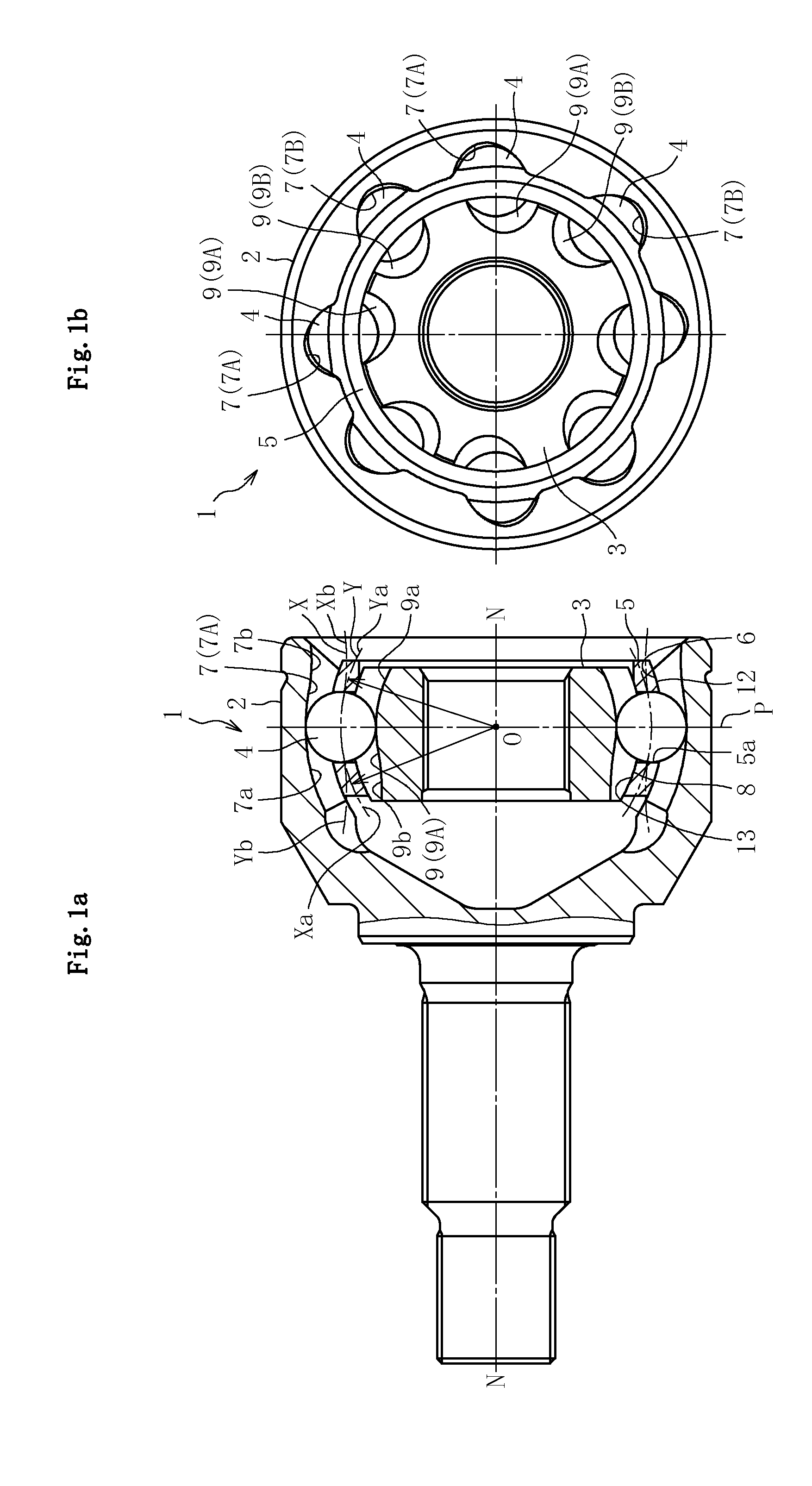
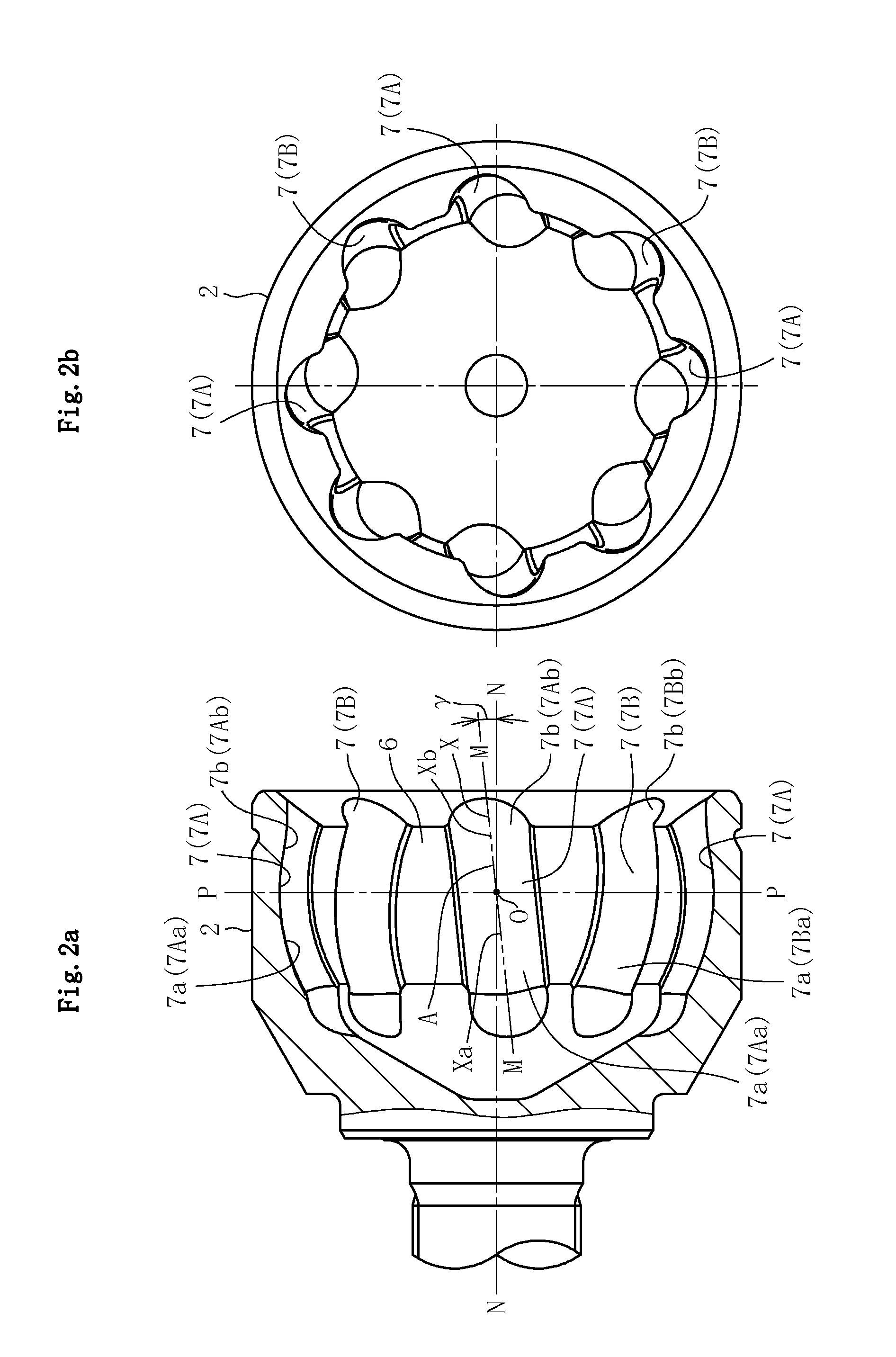
[0078]FIG. 11a is a partial vertical sectional view of the fixed type constant velocity universal joint, and FIG. 11b is a vertical sectional view of the cage. FIG. 11a also illustrates the track grooves 7 and 9 under the state in which the cross-sections are rotated to the inclination angle γ=0° in the plane M illustrated in FIG. 2a and the plane Q illustrated in FIG. 3b. A curvature center Oc1 of the spherical outer peripheral surface 12 of the cage 5 and a curvature center Oc2 of the spherical inner peripheral surface 13 thereof are each offset by f3 in the axial direction with respect to the joint center O. With this offset configuration, the cage 5 can be increased in thickness toward the opening side, and the cage 5 can be increased in strength particularly at high operating angles. As described above, in the range of the high operating angles, the balls 4 arranged in the circumferential direction are temporarily separately located between the first track groove portions 7Aa a...
fifth embodiment
[0085]In the fifth embodiment described above, the ball-raceway center line Xb of each of the second track groove portions 7Ab and 7Bb of the outer joint member 2 is connected smoothly to the end portion A on the opening side of the ball-raceway center line Xa of corresponding one of the first track groove portions 7Aa and 7Ba thereof. Then, the ball-raceway center line Xb is gently curved in a manner that the inclination angle thereof becomes gradually lower toward the opening side, and the inclination angle reaches 0° near the opening rim portion. On the other hand, the ball-raceway center line Yb of each of the second track groove portions 9Ab and 9Bb of the inner joint member 3 is connected smoothly to the end portion B on the depth side of the ball-raceway center line Ya of corresponding one of the first track groove portions 9Aa and 9Ba thereof. Then, the ball-raceway center line Yb is gently curved in a manner that the inclination angle thereof becomes gradually lower toward ...
PUM
 Abstract
Description
Claims
Application Information
 - R&D
- Intellectual Property
- Life Sciences
- Materials
- Tech Scout
- Unparalleled Data Quality
- Higher Quality Content
- 60% Fewer Hallucinations
Browse by: Latest US Patents, China's latest patents, Technical Efficacy Thesaurus, Application Domain, Technology Topic, Popular Technical Reports.
© 2025 PatSnap. All rights reserved.Legal|Privacy policy|Modern Slavery Act Transparency Statement|Sitemap|About US| Contact US: help@patsnap.com


