
Appearance Inspection Device, Appearance Inspection Method, And Program

a technology for appearance inspection and inspection methods, applied in image enhancement, instruments, image data processing, etc., can solve the problems of user workload, heavy burden on users, and increased workload in proportion to the number of pins, so as to reduce the burden on users

Active Publication Date: 2014-03-20
KEYENCE
View PDF13 Cites 23 Cited by
  • Summary
  • Abstract
  • Description
  • Claims
  • Application Information

AI Technical Summary

Benefits of technology

The patent aims to reduce the burden on a user by referring to a measurement region set for one measurement tool among multiple tools used by an appearance inspection device as a reference for another tool. This can make the inspection process more efficient and user-friendly.

Problems solved by technology

Consequently, a user's workload is also increased in proportion to the number of pins.
In the former case, complex repetitive work occurs and a burden on the user is heavy.

Method used


Image

  • Appearance Inspection Device, Appearance Inspection Method, And Program
  • Appearance Inspection Device, Appearance Inspection Method, And Program
  • Appearance Inspection Device, Appearance Inspection Method, And Program

Examples


Embodiment Construction

[0084]Embodiments of the present invention will be described below. Each embodiment described below will help understanding of various concepts such as the generic concept, intermediate concept, and subordinate concept of the present invention. Also, the technical scope of the present invention is settled by the scope of the claims, and is not limited to each embodiment described below.

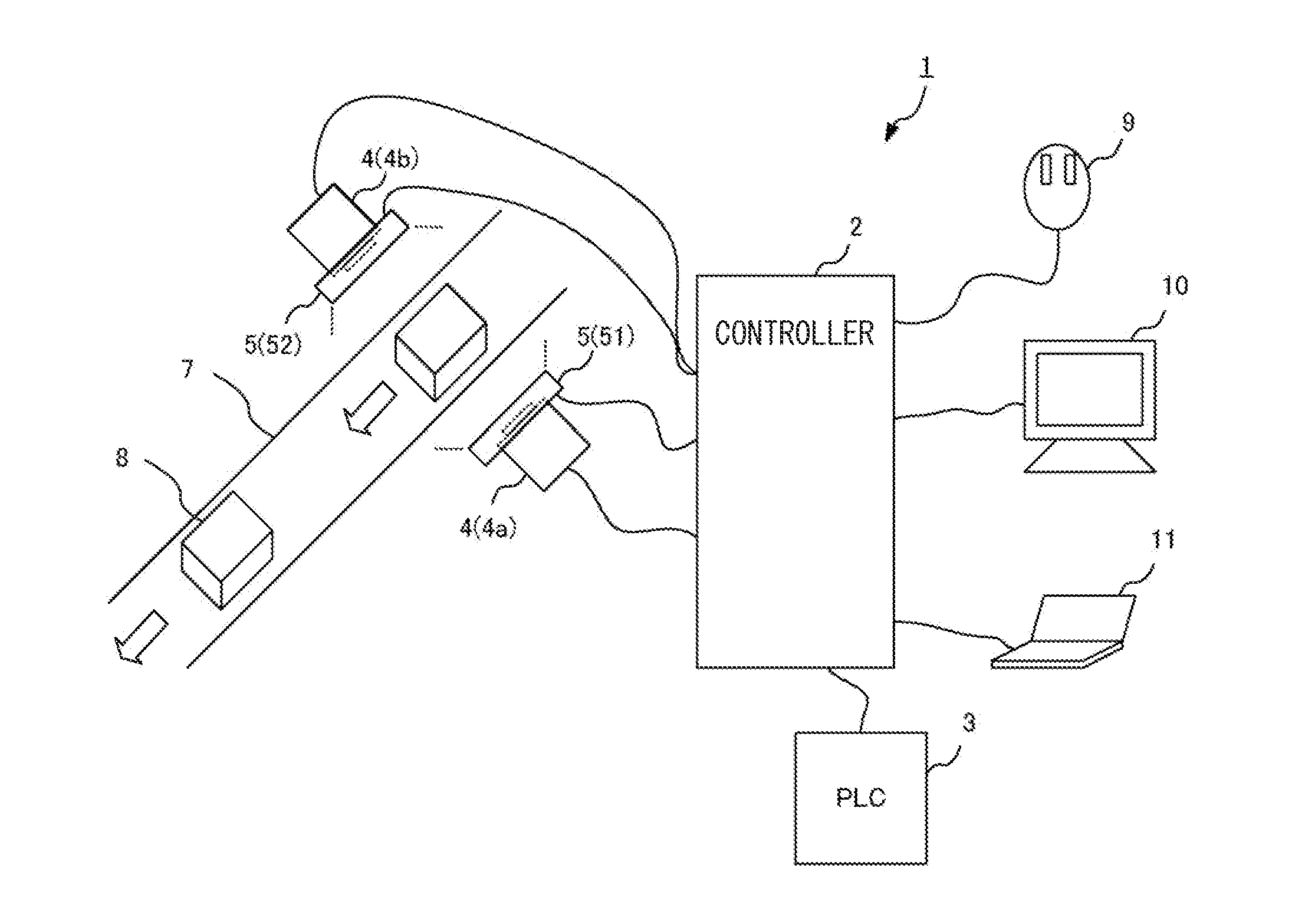
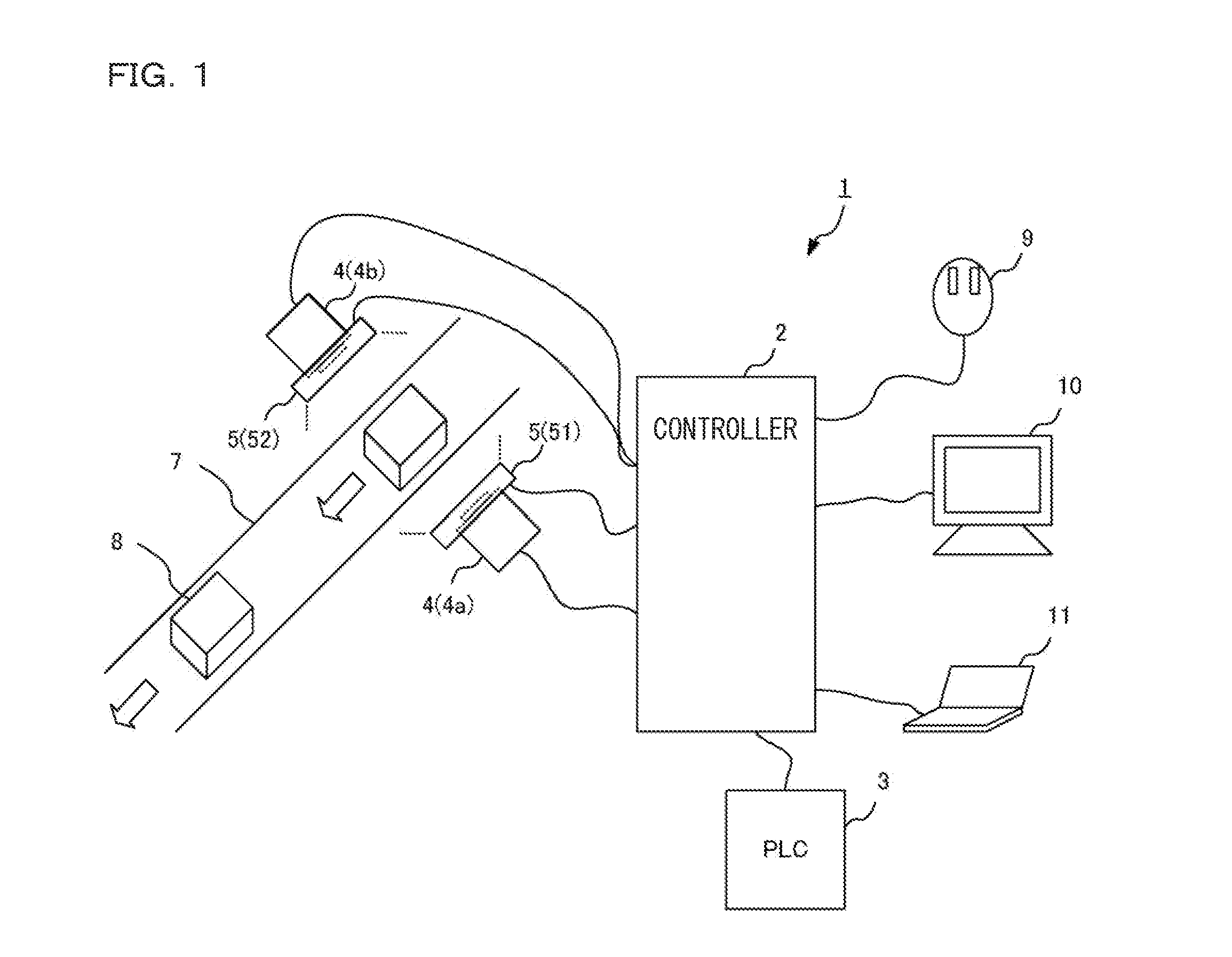
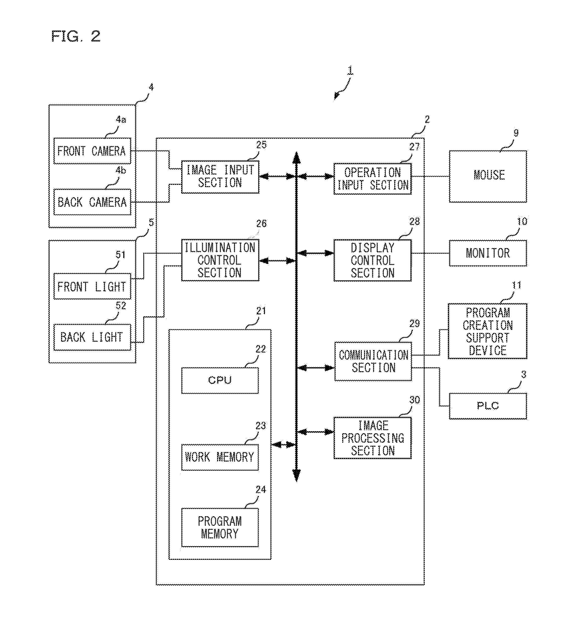
[0085]FIG. 1 is a schematic diagram illustrating an outline of an appearance inspection device 1. The appearance inspection device 1 includes a controller 2, a programmable logic controller (PLC) 3, cameras 4, illuminating devices 5 (a front light 51 and a back light 52), a mouse 9, a monitor 10, and a program creation support device 11. An inspection object 8 is conveyed by a conveyor device 7 such as a belt conveyor to be controlled by the PLC 3, and the inspection object 8 illuminated by the illuminating device such as the front light 51 or the back light 52 is imaged by the camera 4. According to ...


PUM


Abstract

A burden on a user is reduced by referring to a measurement region set for a certain measurement tool among a plurality of measurement tools to be used by an appearance inspection device as a measurement region of another measurement tool. A reference point or a search region serving as a reference of measurement for a first measurement tool such as a connector dimension inspection tool is set for a basic image acquired by imaging a non-defective product. Next, a second measurement tool such as an area measurement tool that performs measurement separate from the first measurement tool is selected by the user. For coordinate data of a measurement region, which is a region to be measured by the second measurement tool, coordinate data of the reference point or the search region set for the first measurement tool is adjusted if necessary and referred to.

Description

CROSS-REFERENCE TO RELATED APPLICATIONS[0001]The present application claims foreign priority based on Japanese Patent Application No. 2012-202271, filed Sep. 14, 2012, the contents of which is incorporated herein by reference.BACKGROUND OF THE INVENTION[0002]1. Field of the Invention[0003]The present invention relates to an appearance inspection device, an appearance inspection method, and a program for inspecting an appearance of a product by imaging the product.[0004]2. Description of Related Art[0005]A so-called product appearance inspection is performed by imaging an appearance of a product such as a connector or a semiconductor element and performing pattern matching (image recognition). The product may not be within an imaging range of a camera depending on a size of the product, and an image representing the entire product is created by connecting a plurality of images for such a product to perform an appearance inspection (Japanese Unexamined Patent Publication Nos. H06-1673...

Claims


Application Information

Patent Timeline
IPC IPC(8): G01N21/88
CPCG01N21/88G06T7/001G06T2207/20092G06T2207/30148G06V10/987G06V2201/06
Inventor IKUSHIMA, YASUHISA
Owner KEYENCE
Learn More