
Image processing method and image processing apparatus

a technology of image processing and image, applied in the direction of electrical equipment, duplicate/marking methods, printing, etc., can solve the problems of reducing the color density of filling areas, reducing the durability of cycle and erasability, and reducing image erasing time. , to achieve the effect of increasing cycle durability and erasability and reducing image erasing tim

Inactive Publication Date: 2014-03-20
RICOH KK
View PDF12 Cites 6 Cited by
  • Summary
  • Abstract
  • Description
  • Claims
  • Application Information

AI Technical Summary

Benefits of technology

[0026]An object of the present invention is to provide an image processing method capable of increasing cycle durability and erasability and of reducing image-erasing time, and an image processing apparatus using the image processing method.
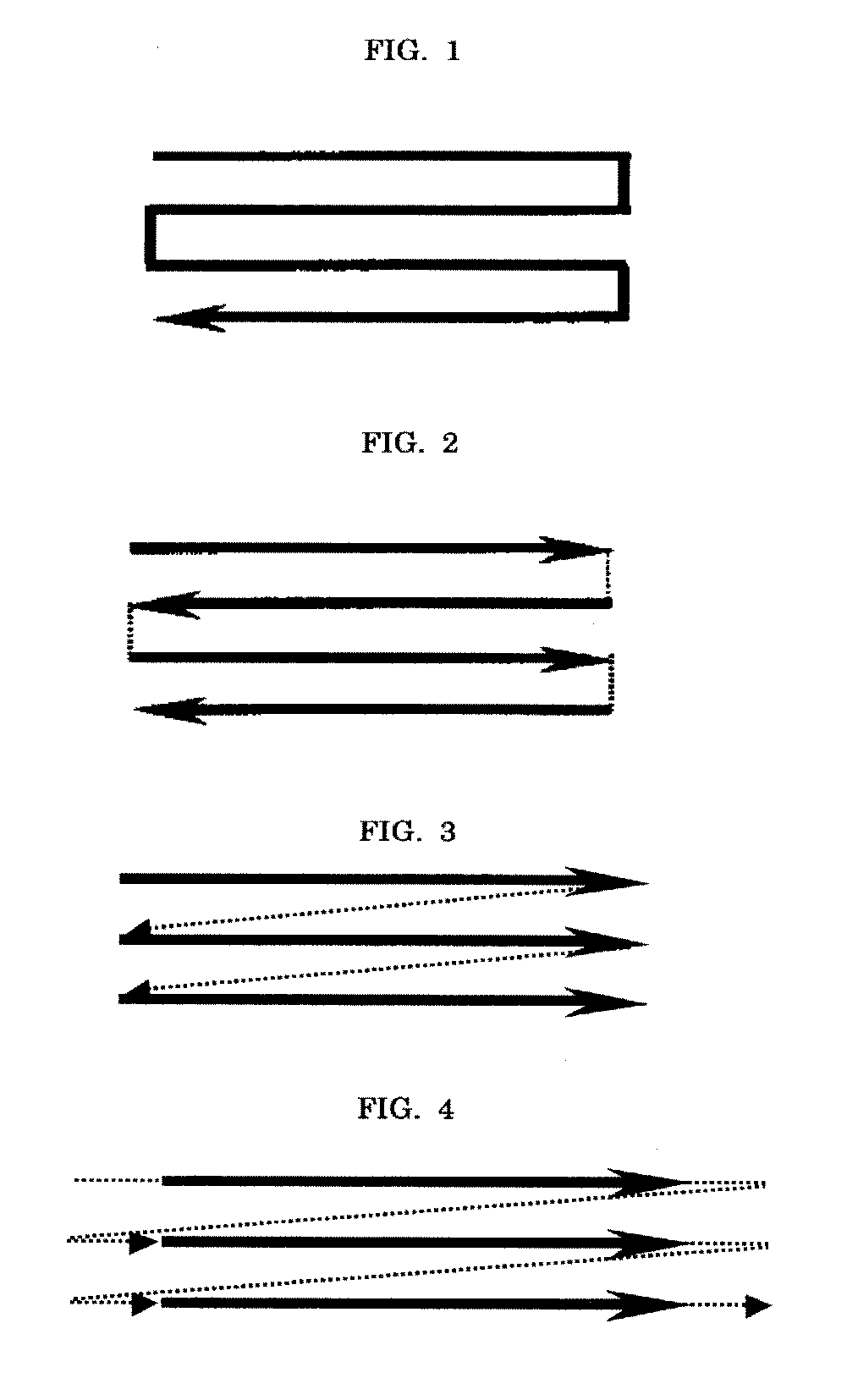
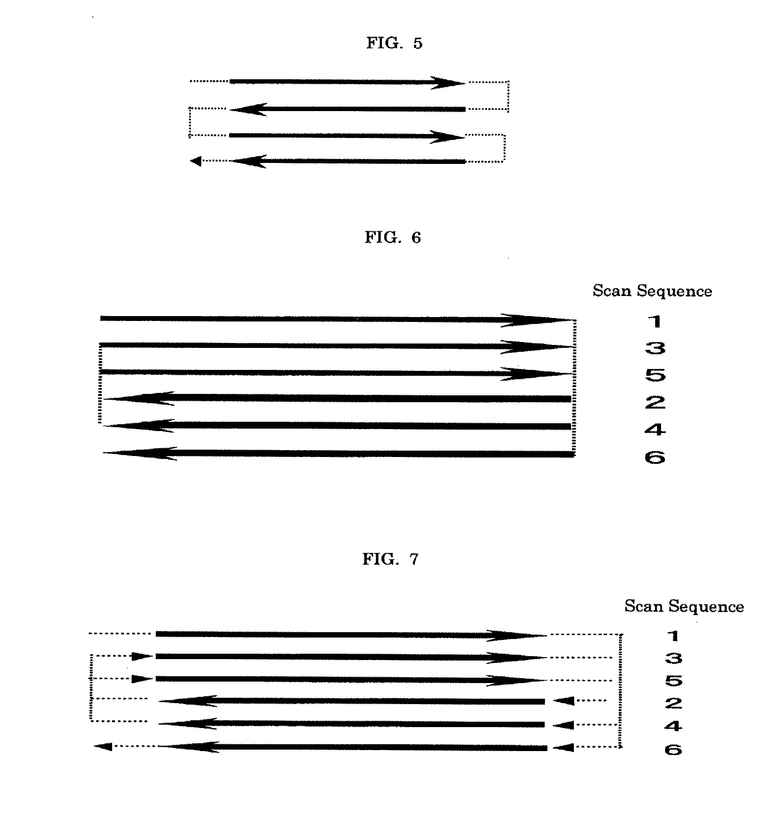
[0045]In the image processing method according to any one of the first to fourth aspects of the present invention, laser beams are applied sequentially or randomly over a medium in the same direction or alternating directions, and furthermore, this laser scanning involves a period where laser application is discontinued, thereby achieving formation or erasing of an image. Furthermore, it is possible to avoid accumulation of extra energy in areas where laser scanning turns back and / or areas where laser beams are overlapped.
[0047]In the image processing apparatus, the laser application unit emits a laser beam, and the laser beam adjusting unit changes the light intensity of the laser emitted from the laser application unit. As a result, the degradation of a thermoreversible recording medium due to repetitive cycles of image recording and image erasing can be effectively prevented.

Problems solved by technology

Although laser printing and laser erasing can be performed by the methods described above, there remains a problem of occurrence of local heat damages when lines are overlapped during printing and a problem of reduced color developing density in filled-in areas, because laser control is not performed during printing.
Moreover, when displacement occurs, it results in an occasion where some portions of the image are not erased.
Displacement is likely to occur particularly in cases where an image is printed or erased on or from an moving article, which may result in erasing failure.
However, the image erasing method disclosed in JP-A No. 2001-88333 leads to degradation of media and reduction in the cycle durability.
In either case, it is very difficult to immediately stop a laser beam in turn back areas; thus, the scan speed is gradually slowed down there.
For this reason, in conventional scanning strategies, the laser beam slows down in the turn back areas, so too does the scan speed, thereby imparting excessive energy to the turn back areas and promoting them to a high-energy state.
In addition, since the laser beam is immediately applied to the nearby portion, i.e., the start point of the next laser scanning (line) without stopping laser irradiation, extremely excessive energy is imparted to the turn back area.
For this reason, it still results in application of excessive energy to the turn back area, promoting media degradation and reducing cycle durability (e.g., see FIG. 2).
The turn back areas of the thermoreversible recording medium, high-temperature areas due to application of excessive energy, may be susceptible to generation of background fogs due to color developemnt.
Thus it takes much time to erase an image, depending on the size of the image.

Method used


Image

  • Image processing method and image processing apparatus
  • Image processing method and image processing apparatus
  • Image processing method and image processing apparatus

Examples


preparation example 1

[0326]A thermoreversible recording medium that offers temperature-dependent reversible changes in color tone (between clear state and color-developed state) was prepared as follow.

—Support—

[0327]A milky polyester film (Tetron Film U2L98W by Teijin Dupont Films Japan Ltd.) of 125 μm thickness was used as a support.

—Under Layer—

[0328]A coating solution for under layer was prepared by mixing together 30 parts by mass of styrene-butadiene copolymer (PA-9159 by Nippon A&L Inc.), 12 parts by mass of polyvinyl alcohol resin (Poval PVA103 by Kuraray Co., Ltd.), 20 parts by mass of hollow particles (Microsphere R-300 by Matsumoto Yushi-Seiyaku Co., Ltd.) and 40 parts by mass of water, followed by 1 hour stirring until homogenous.

[0329]Next, the support was coated with the obtained coating solution for under layer by means of a wire bar, heated at 80° C. for 2 minutes and dried to form an under layer of 20 μm thickness.

—Reversible Thermosensitive Recording Layer (Recording Layer)—

[0330]Five p...

preparation example 2

[0339]A thermoreversible recording medium that offers temperature-dependent reversible changes in transparency (between clear state and clouded state) was prepared as follow.

—Support—

[0340]A transparent PET film (Lumilar 175-T12 by Toray Industries, Inc.) of 175 μm thickness was used as a support.

—Reversible Thermosensitive Recording Layer (Recording Layer)—

[0341]In a glass bottle, 3 parts by mass of low-molecular-weight organic substance represented by the following Structural Formula (5) and 7 parts by mass of docosyl benenate were added in a resin solution containing 26 parts by mass of vinyl chloride copolymer (M110 by Zeon Corp.) dissolved in 210 parts by mass of methyl ethyl ketone. Ceramic beads of 2 mm diameter were placed in the glass bottle, followed by dispersing treatment for 48 hours by using a paint shaker (by Asada Iron Works, Co., Ltd.). In this way a uniform dispersion solution was obtained.

[0342]Next, 4 parts by mass of isocyanate compound (Colonate 2298-90T by Nip...

preparation example 3

[0345]A thermoreversible recording medium of Preparation Example 3 was prepared as in Preparation Example 1 except that 0.03 parts by mass of photothermal conversion material (Excolor®IR-14 by Nippon Shokubai Co., Ltd.) was added in the recording layer upon fabrication of the thermoreversible recording medium.


PUM

PropertyMeasurementUnit
timeaaaaaaaaaa
diameteraaaaaaaaaa
diameteraaaaaaaaaa

Abstract

To provide an image processing method including at least one of an image recording step and an image erasing step, wherein (1) laser beams are swept in the same direction and laser scanning involves a period where laser application is discontinued, (2) laser beams are swept in alternating directions and the laser scanning involves a period where laser application is discontinued, (3) laser beams are swept in alternating directions and laser scanning involves a period where laser application is discontinued, wherein the period involves no laser beam application from first laser scanning end point to second laser scanning point, or (4) laser beams are applied in alternating directions while avoiding continuous laser irradiation of nearby portions between adjacent laser beam lines, and laser scanning involves a period where laser application is discontinued.

Description

BACKGROUND OF THE INVENTION[0001]1. Field of the Invention[0002]The present invention relates to an image processing method capable of increasing cycle durability and erasability and of reducing image-erasing time, and to an image processing apparatus using the image processing method.[0003]2. Description of the Related Art[0004]A non-contacting laser based method is proposed as a method of creation or deletion of an image on or from a thermoreversible recording medium (hereinafter referred to as “reversible thermal sensitive medium,”“recording medium,” or “medium” in some cases) whose surface has irregularities and as a method of creation or deletion of an image on such a medium at a distance (see Japanese Patent Application Laid-Open (JP-A) No. 2000-136022). This method adopts non-contacting recording on shipping containers used for distribution of goods, wherein the containers are formed of a thermoreversible recording medium, a laser is used for recording (writing) of image, and...

Claims


Application Information

Patent Timeline
Patent Type & Authority Applications(United States)
IPC IPC(8): B41M7/00
CPCB41M7/009B41J2/473B41J2/4753B41M5/305H04N1/00
Inventor KAWAHARA, SHINYAISHIMI, TOMOMIHOTTA, YOSHIHIKO
Owner RICOH KK
Learn More