Standoff generating devices and processes for making same
- Summary
- Abstract
- Description
- Claims
- Application Information
AI Technical Summary
Benefits of technology
Problems solved by technology
Method used
Image


Examples
example 1
Standoff Generation without Fillers with Thermal Cure
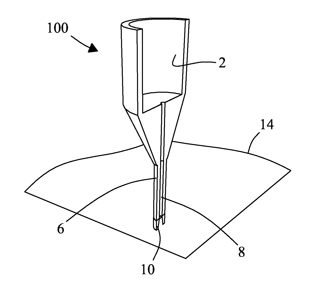
[0098]A shape-forming material mixture was prepared without fillers by thoroughly stirring 10 g of EPO-TEK® 377 Part A epoxidized diol (Epoxy Technology, Inc., Billerica, Mass., USA) and 10 g of EPO-TEK® 377 Part B anhydride (Epoxy Technology, Inc., Billerica, Mass., USA) to produce a mixture with a viscosity between about 100 centipoise (cP) and 300 centipoise (cP). The viscous mixture was loaded into the reservoir 2 of standoff generating device 100. A glass pane surface 14 with dimensions 6 inches (15 cm) by 6 inches (15 cm) was positioned below the dispensing device 100 and the dispensing tip 10 was subsequently brought in contact with the pane 14. The shape-forming epoxy mixture was dispensed from the dispensing tip 10 with a pulse of pneumatic pressure. A 3 inch (7.5 cm) by 3 inch (7.5 cm) grid of standoffs 16 composed of the shape-forming material was dispensed onto the receiving surface 14 with a spacing of 5 mm between in...
example 2
Standoff Generation with Fillers with Thermal Cure
[0099]A shape-forming material mixture was prepared containing fillers to provide a selective thermal cure and a standoff with suitable mechanical properties by thoroughly stirring 10 g of EPO-TEK® 377 Part A epoxidized diol (Epoxy Technology, Inc., Billerica, Mass., USA), 10 g of EPO-TEK® 377 Part B anhydride (Epoxy Technology, Inc., Billerica, Mass., USA), and 0.5 g Nanomer® I.28E modified montmorillonite nanoclay (filler) (Nanocor, Inc., Hoffman Estates, Ill., USA) to produce a mixture with a viscosity greater than 300 cP. The viscous mixture was loaded into the reservoir 2 of standoff generating device 100. A glass pane surface 14 with dimensions 6 inches (15 cm) by 6 inches (15 cm) was positioned below the dispensing device 100 and the dispensing tip 10 was subsequently brought in contact with the pane surface 14. The shape-forming epoxy mixture was dispensed from the dispensing tip 10 with a pulse of pneumatic pressure. A 3 inc...
example 3
Standoff Generation without Fillers with UV Cure
[0100]A shape-forming material mixture was prepared without fillers to provide a selective photo cure to produce standoffs with suitable mechanical properties. DYMAX® UltraLight-Weld® OP-4-20632 polyester acrylate (Dymax Corp., Torrington, Conn., USA) was loaded into the reservoir 2 of standoff generating device 100. A glass pane surface 14 with dimensions 6 inches (15 cm) by 6 inches (15 cm) was positioned below the dispensing device 100 and the dispensing tip 10 was subsequently brought in contact with the pane surface 14. The shape-forming epoxy mixture was dispensed from the dispensing tip 10 with a pulse of pneumatic pressure. A 3 inch (7.5 cm) by 3 inch (7.5 cm) grid of standoffs 16 composed of the shape-forming material was dispensed onto the receiving surface 14 with a spacing of 5 mm between individual standoffs 16. A UV source 20 positioned below the transparent receiving surface 14 was employed to pre-cure the shape-forming ...
PUM
| Property | Measurement | Unit |
|---|---|---|
| Temperature | aaaaa | aaaaa |
| Density | aaaaa | aaaaa |
| Shape | aaaaa | aaaaa |
Abstract
Description
Claims
Application Information
 - R&D
- Intellectual Property
- Life Sciences
- Materials
- Tech Scout
- Unparalleled Data Quality
- Higher Quality Content
- 60% Fewer Hallucinations
Browse by: Latest US Patents, China's latest patents, Technical Efficacy Thesaurus, Application Domain, Technology Topic, Popular Technical Reports.
© 2025 PatSnap. All rights reserved.Legal|Privacy policy|Modern Slavery Act Transparency Statement|Sitemap|About US| Contact US: help@patsnap.com