
Steel piston with counter-bore design

a technology of counterbore and steel piston, which is applied in the direction of pistons, machines/engines, mechanical equipment, etc., can solve the problems of increasing combustion temperature and pressure, reducing the wall thickness of the skirt, and damage to aluminum pistons, so as to reduce the total weight or mass of the piston body, reduce material costs, and reduce the effect of weight or mass added to the piston body by the ribs

Active Publication Date: 2014-03-20
TENNECO
View PDF2 Cites 11 Cited by
  • Summary
  • Abstract
  • Description
  • Claims
  • Application Information

AI Technical Summary

Benefits of technology

The invention relates to reducing the weight of an automotive piston through designing its structure with thinner walls and optimal placement of reinforcing elements like ribs. By locating these elements at the bottom of the piston where they serve their function without adding much extra weight, the overall weight of the piston can be minimized while still maintaining sufficient strength for use in high-performance engines. This reduces materials usage and improves fuel efficiency during production.

Problems solved by technology

The technical problem addressed in this patent text is how to manufacture pistons with advanced technologies, such as direct injection and turbo-charging, while resisting damage caused by increased combustion temperatures and pressures without compromising the material strength of the piston body. Specifically, the text discusses the challenge of machining counter-bore surfaces into skirts with reduced wall thicknesses while avoiding the creation of thin, brittle and sharp outer, non-machined surfaces that could be easily damaged during the subsequent machining operations or handling prior to or after the machining operations.

Method used


Image

  • Steel piston with counter-bore design
  • Steel piston with counter-bore design
  • Steel piston with counter-bore design

Examples


Embodiment Construction

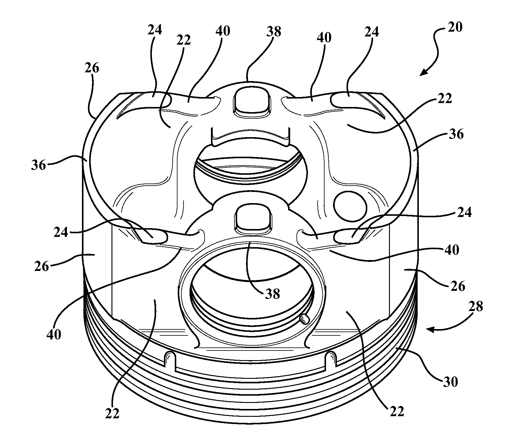
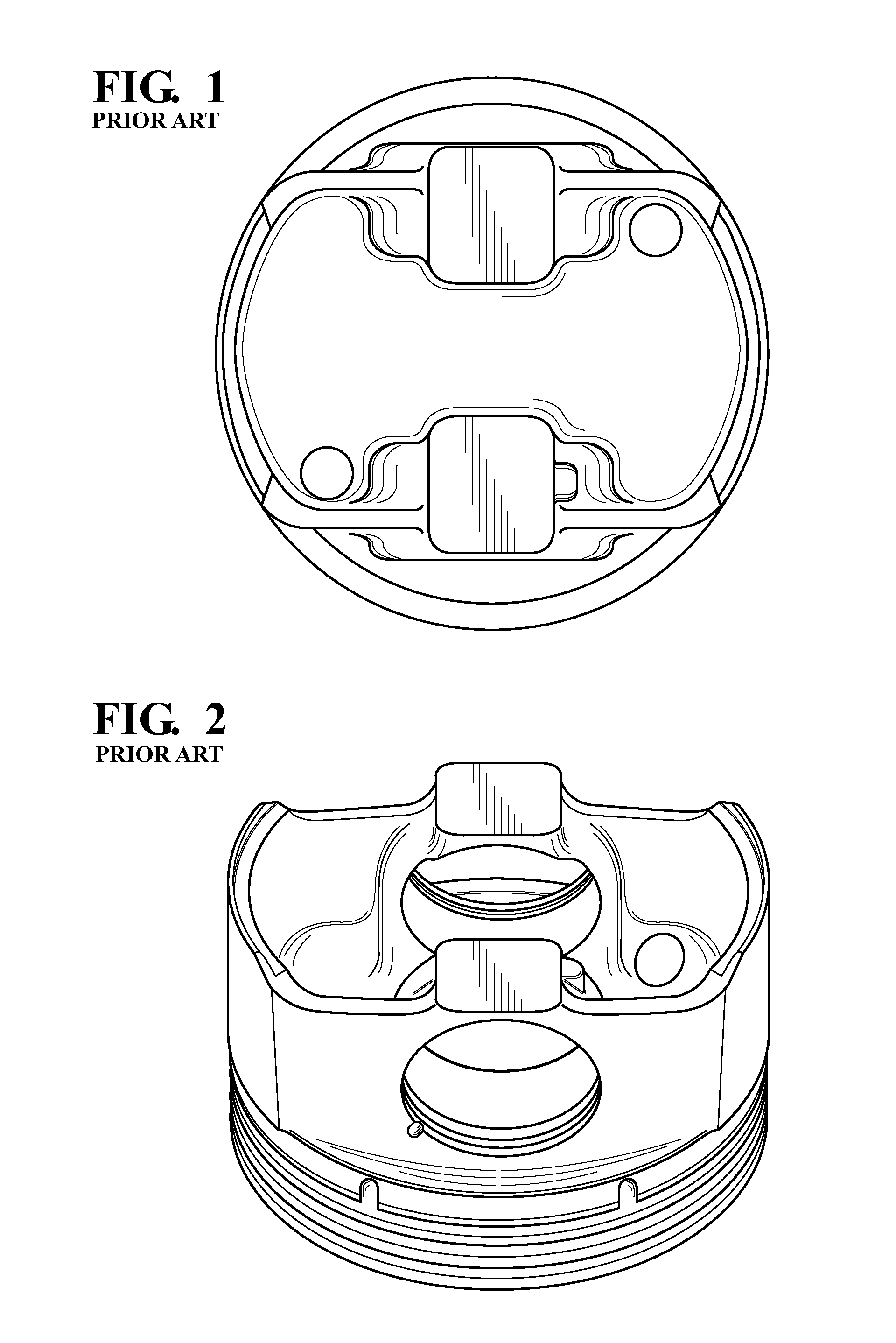
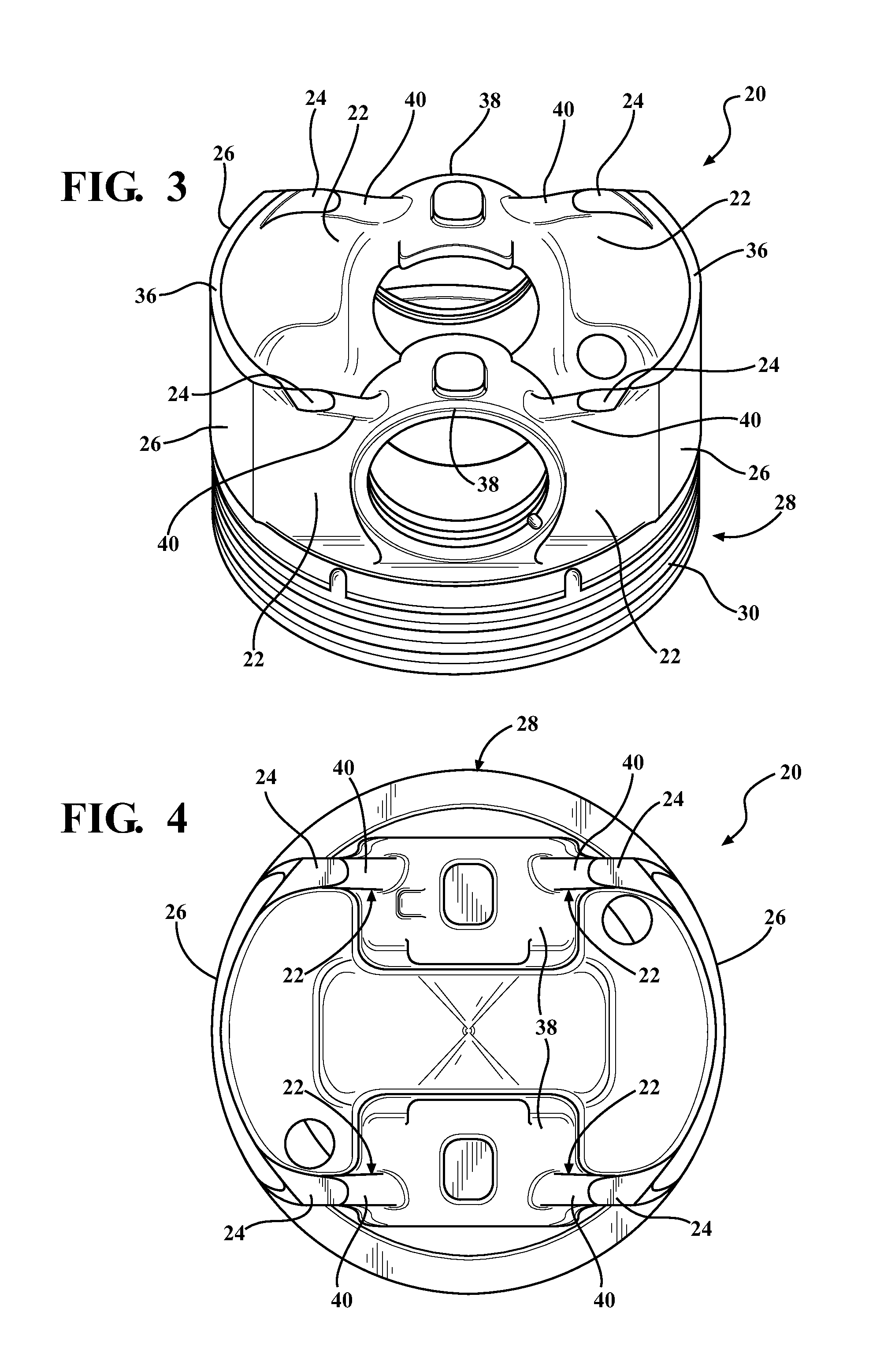
[0016]Referring to the Figures, wherein like numerals indicate corresponding parts throughout the several views, an exemplary embodiment of a monobloc piston body 20 for an internal combustion engine (not shown) is generally shown in FIGS. 3-5. The exemplary embodiment of the piston body 20 is made of steel and has a plurality of pin boss bridges 22 with generally flat counter-bore surfaces 24 which are machined into the pin boss bridges 22 after a casting and / or forging operation. The generally flat counter-bore surfaces 24 on the pin boss bridges 22 may be used as datum and / or reference locations for subsequent machining operations on the piston body 20. Additionally, because the generally flat counter-bore surfaces 24 are formed on the pin boss bridges 22 rather than on skirts 26 of the piston body 20, the skirts 26 may be formed with a reduced or optimized wall thickness as compared to other known piston bodies made of steel.

[0017]Referring now to FIG. 3, the piston body 20 of t...


PUM

PropertyMeasurementUnit
Thicknessaaaaaaaaaa
Shapeaaaaaaaaaa

Abstract

A piston for an internal combustion engine is provided. The piston includes a piston body which is made of steel. The piston body has a crown portion with an upper combustion surface, a pair of skirts which depend from the crown surface, a pair of pin bosses for receiving a wrist pin and a plurality of pin boss bridges which extend from the pin bosses to the skirts. Each of the pin boss bridges extends axially to a lower end which is opposite of the crown portion and has a rib with an increased thickness at its lower end. At least one of the pin boss bridges has a generally flat counter-bore surface for providing a reference location for machining of the piston body.

Description


Claims


Application Information

Patent Timeline
Owner TENNECO
Learn More