
Device for reliable filling level control in a quenching chamber that is arranged downstream of entrained-flow gasification and has inert-gas flushing of the pressure-recording measuring location

a technology of level control and quenching chamber, which is applied in the direction of process and machine control, functional valve types, instruments, etc., can solve the problems of measurement value not being produced or falsified, and achieve the effect of improving the reliability of filling level control

Active Publication Date: 2014-03-13
SIEMENS ENERGY GLOBAL GMBH & CO KG
View PDF6 Cites 3 Cited by
  • Summary
  • Abstract
  • Description
  • Claims
  • Application Information

AI Technical Summary

Benefits of technology

The invention aims to improve the reliability of filling level control in a quenching chamber. It achieves this by measuring the pressures in the chamber as controlled variables, even in cases where there is a risk of blockages due to deposits. The invention also increases the dependability and reliability of measuring the height of the filling level in the quenching chamber by flushing the measuring location. This reduces the risk of raw gas entering the overflow or an overflow of the water bath into the raw-gas outlet.

Problems solved by technology

A possible breakthrough of raw gas into the excess water line 3 represents a safety problem, since the downstream soot water installation is not designed for synthesis gas.
The sensing of the pressures mentioned is susceptible to problems due to the formation of deposits and accompanying blockages of the measuring lines leading to the transmitter 6, both to the quencher sump 2 and also from the quenching chamber 1, with the result that the measured values are not produced or are falsified, which can lead to the aforementioned operational problems.

Method used


Image

  • Device for reliable filling level control in a quenching chamber that is arranged downstream of entrained-flow gasification and has inert-gas flushing of the pressure-recording measuring location
  • Device for reliable filling level control in a quenching chamber that is arranged downstream of entrained-flow gasification and has inert-gas flushing of the pressure-recording measuring location
  • Device for reliable filling level control in a quenching chamber that is arranged downstream of entrained-flow gasification and has inert-gas flushing of the pressure-recording measuring location

Examples


Embodiment Construction

[0016]In the figures, the same designations designate the same elements.

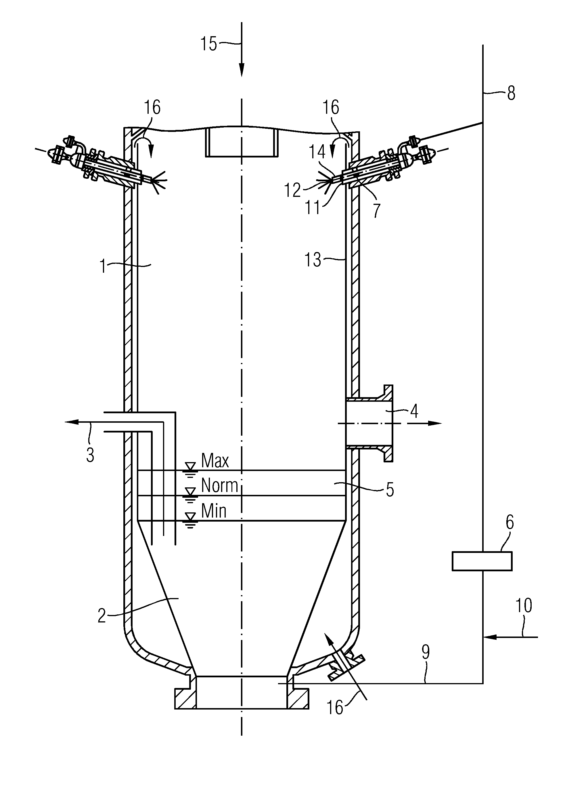
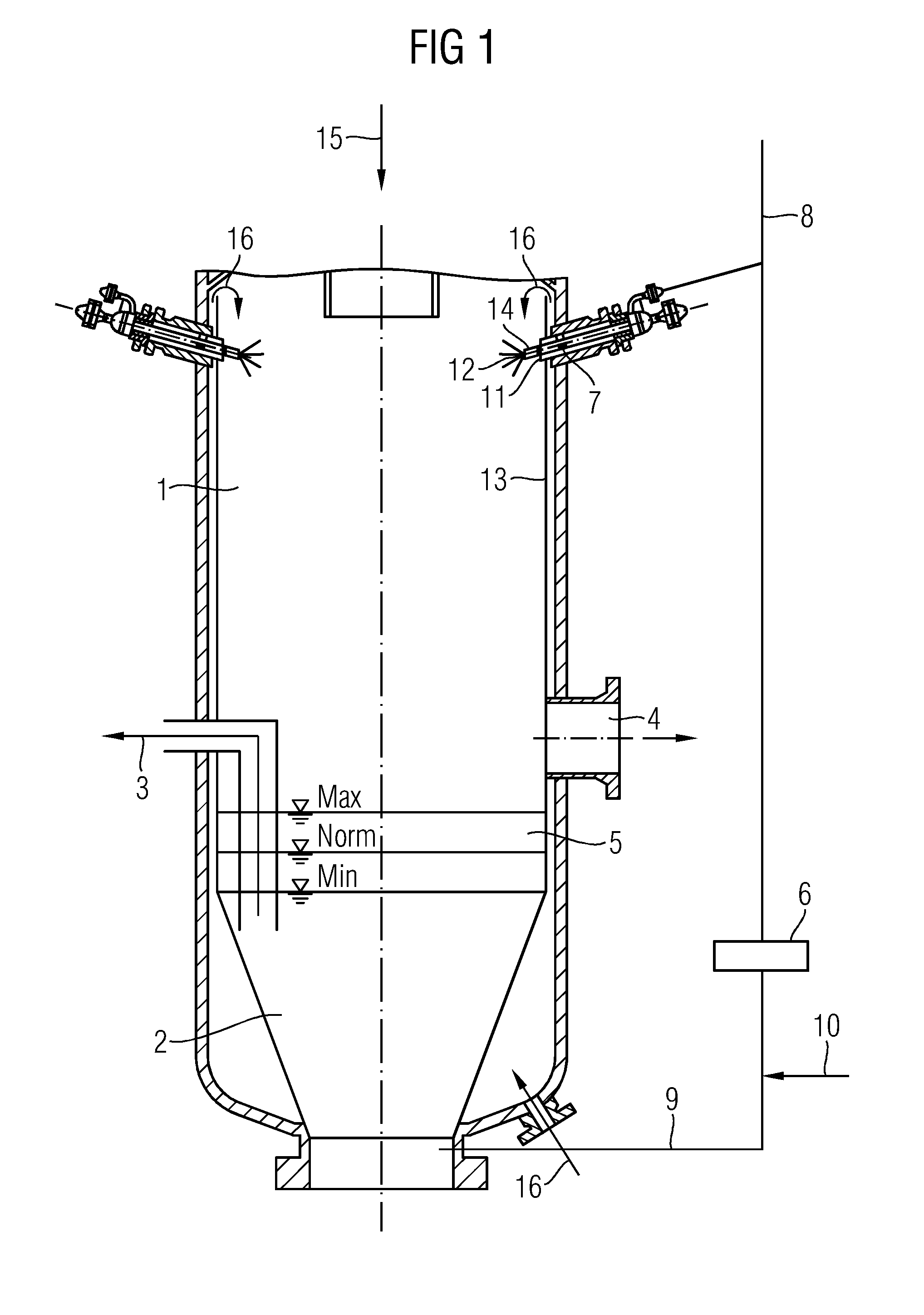
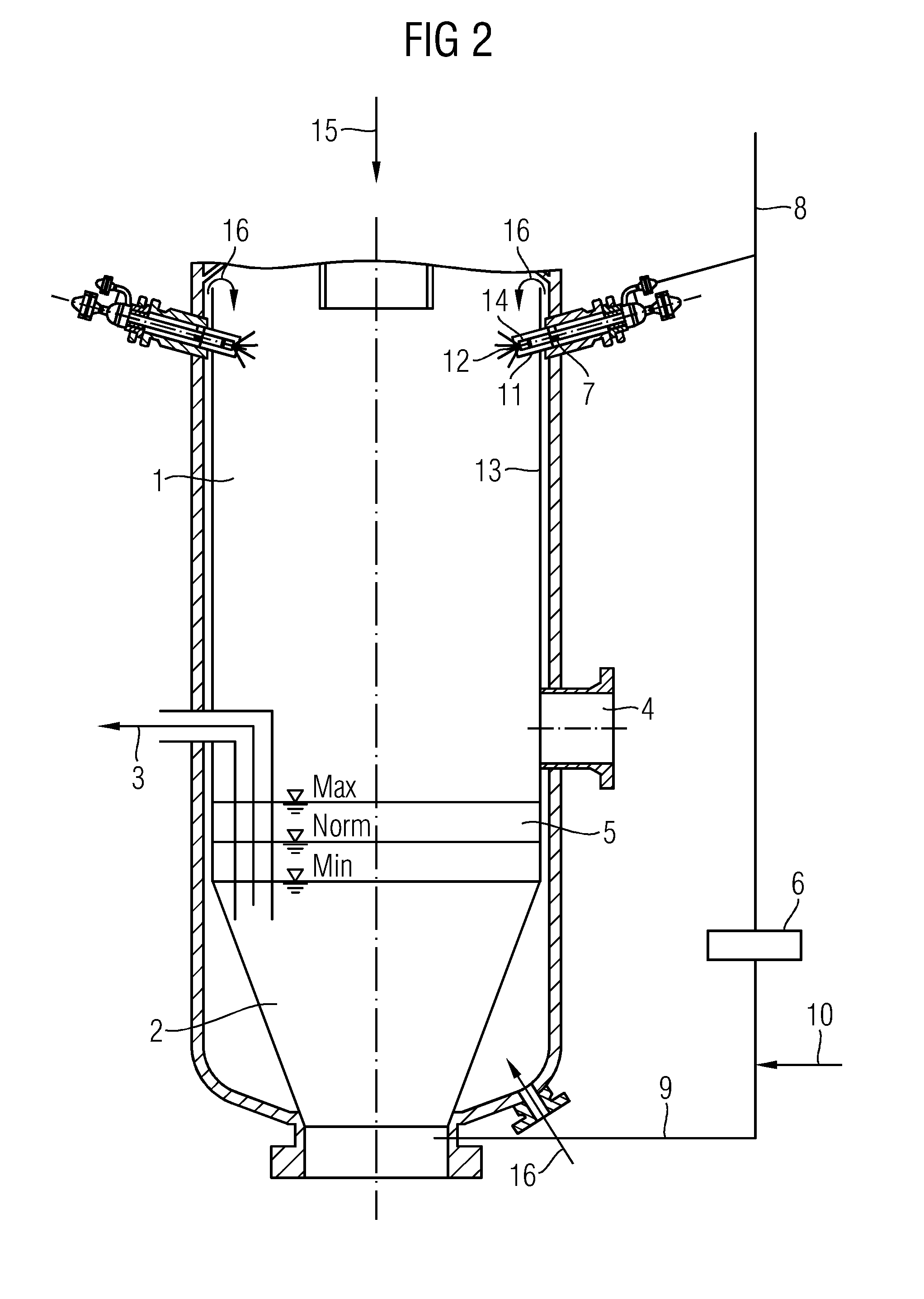
[0017]The quenching arrangement represented in FIG. 1 for an entrained-flow gasifier is formed by an outer pressure-bearing shell, which receives an inner shell as a skirt 13. Between the outer shell and the inner shell there is a skirt flushing 16, the overflow of which takes place at the upper end of the inner shell into the interior of the skirt. In the lower part of the skirt there is a water bath 2, which is controlled between a minimum water level Min, the normal water level Norm and the maximum water level Max. Distributed in the upper region of the quencher are a number of quenching nozzles 7, which are distributed over the circumference and inject quenching water through the outer shell and the inner shell into the quenching chamber 1.

[0018]On the basis of the measurement of the differential pressure between the gas chamber 1 and the bottom of the water bath 9, as a measure of the geodetic height of the...


PUM


Abstract

A device for the reliable measurement and control of the filling level in the quencher sump of a quenching chamber arranged downstream of the gasifying chamber is provided. The device has a differential-pressure transmitter. The measuring location recording the pressure of the gas chamber is flushed with inert gas. The device unproblematically senses the pressures in the quenching chamber and at the bottom of the quencher sump. The difference between which is used as a controlled variable for the filling level.

Description

CROSS REFERENCE TO RELATED APPLICATIONS[0001]This application claims priority to German application No. 10 2012 215 898.7 DE filed Sep. 07, 2012, the entire content of which is hereby incorporated herein by reference.FIELD OF INVENTION[0002]The invention relates to a device for reliable filling level control in a quencher that receives the hot raw gas and the liquid slag from an entrained-flow gasifying reactor and cools it by injecting an excess of water.BACKGROUND OF INVENTION[0003]The invention relates to a technology for entrained-flow gasification in which solid and liquid fuels are converted by a gasification medium containing free oxygen under pressures of up to 10 MPa and temperatures of up to 1850° C. into an H2- and CO-rich raw gas. The technology has been described in detail in “Die Veredelung und Umwandlung von Kohle” [The upgrading and conversion of coal], issued by the Deutsche Wissenschaftliche Gesellschaft für Erdöl, Erdgas und Kohle e.V. [German Society for Petroleu...

Claims


Application Information

Patent Timeline
Patent Type & Authority Applications(United States)
IPC IPC(8): G05D9/00
CPCG05D9/00G05D9/12Y10T137/7287
Inventor FISCHER, NORBERTHANNEMANN, FRANKJUST, TINOMEHLHOSE, FRIEDEMANNWERNER, JORG
Owner SIEMENS ENERGY GLOBAL GMBH & CO KG
Learn More