
Information processing system, method, and program

a technology of information processing system and program, applied in the field of information processing system, can solve the problems of low operation accuracy of a multi-axial robot with absolute position designation, robots are beginning to perform complicated tasks, and people are not needed to prepare parts feeder equipmen

Active Publication Date: 2014-03-06
CANON KK
View PDF3 Cites 45 Cited by
  • Summary
  • Abstract
  • Description
  • Claims
  • Application Information

AI Technical Summary

Benefits of technology

The patent describes an information processing system that can obtain two-dimensional or three-dimensional information about a target object using two sensors. The system can also measure the position and orientation of the object using three sensors and model information about the object. The technical effect of this patent is to provide a more accurate and precise way of measuring the position and orientation of objects using a variety of sensors and models, which can be useful in various fields such as manufacturing, logistical supply chain management, and medical diagnosis.

Problems solved by technology

With recent progress in robot technology, robots are beginning to perform complicated tasks, instead of people, which had been performed by people in the past such as assembling of industrial products.
However, preparing a parts feeder apparatus requires an additional cost.
This is because an operation accuracy of a multi-axial robot with absolute position designation is low, and occlusion may occur in which one of the sensors cannot observe the component, and thus, the accuracy at the position where the component is grabbed cannot be ensured.
Therefore, the weight of the sensor is added to a load capacity of an arm portion of the robot, and increases the inertia during movement.
As a result, a robot with a higher degree of rigidity is required, which increases the cost.

Method used


Image

  • Information processing system, method, and program
  • Information processing system, method, and program
  • Information processing system, method, and program

Examples


Embodiment Construction

[0018]Various exemplary embodiments, features, and aspects of the invention will be described in detail below with reference to the drawings.

[0019]According to a first exemplary embodiment, a first sensor unit (a projector and a camera) for obtaining three-dimensional information about a target object and a second sensor unit (a camera) which is attached to a robot and for obtaining two-dimensional information about the target object are used to measure three-dimensional position and orientation of the target object.

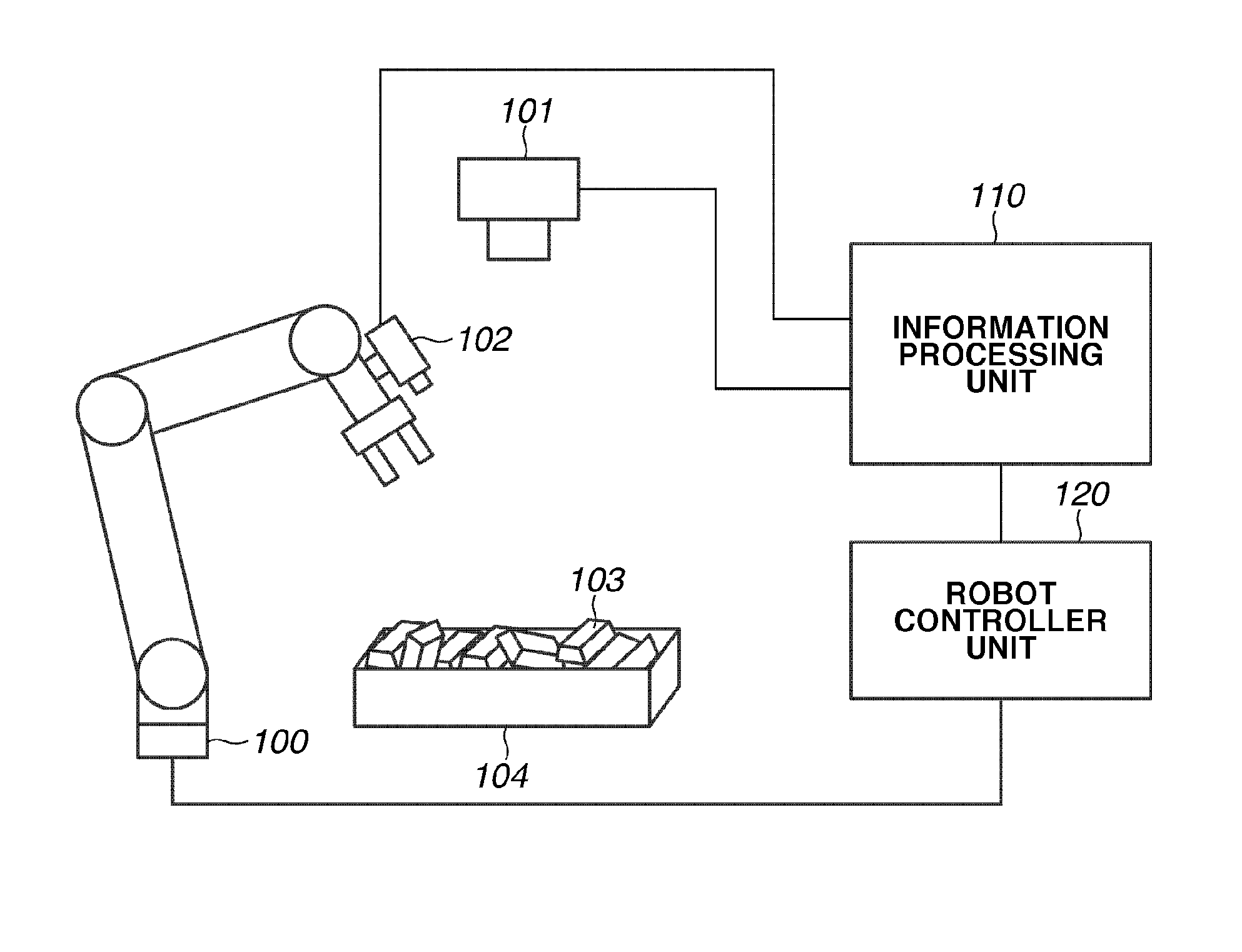
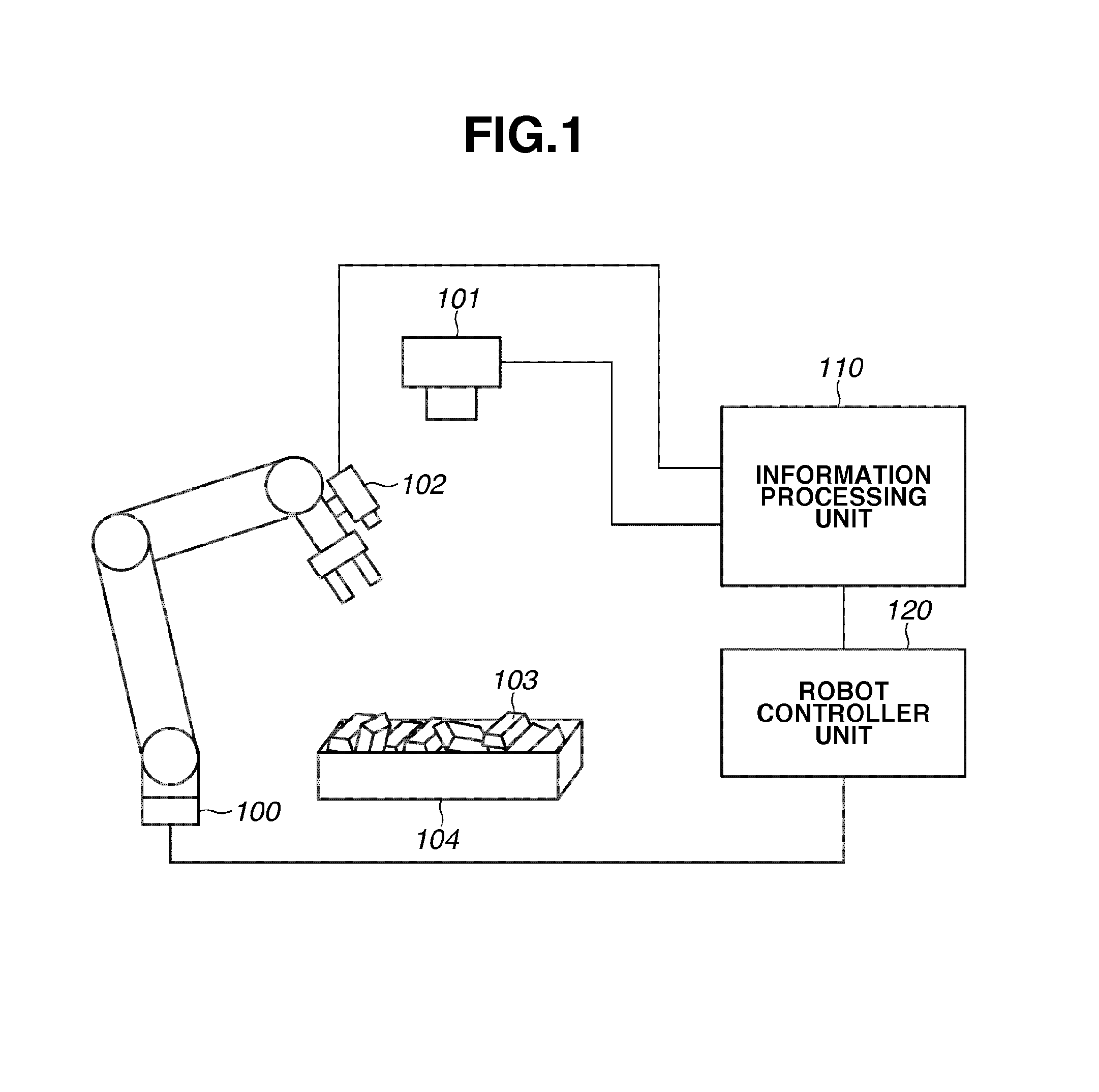
[0020]FIG. 1 illustrates a configuration of a control system of a robot according to the first exemplary embodiment. As illustrated in FIG. 1, the control system is provided with a robot 100 and an information processing system including a first sensor unit 101, a second sensor unit 102, an information processing unit 110, and a robot controller unit 120. With this configuration, a target object 103 stacked in a pallet 104 is measured, and the robot 100 performs pickup o...


PUM


Abstract

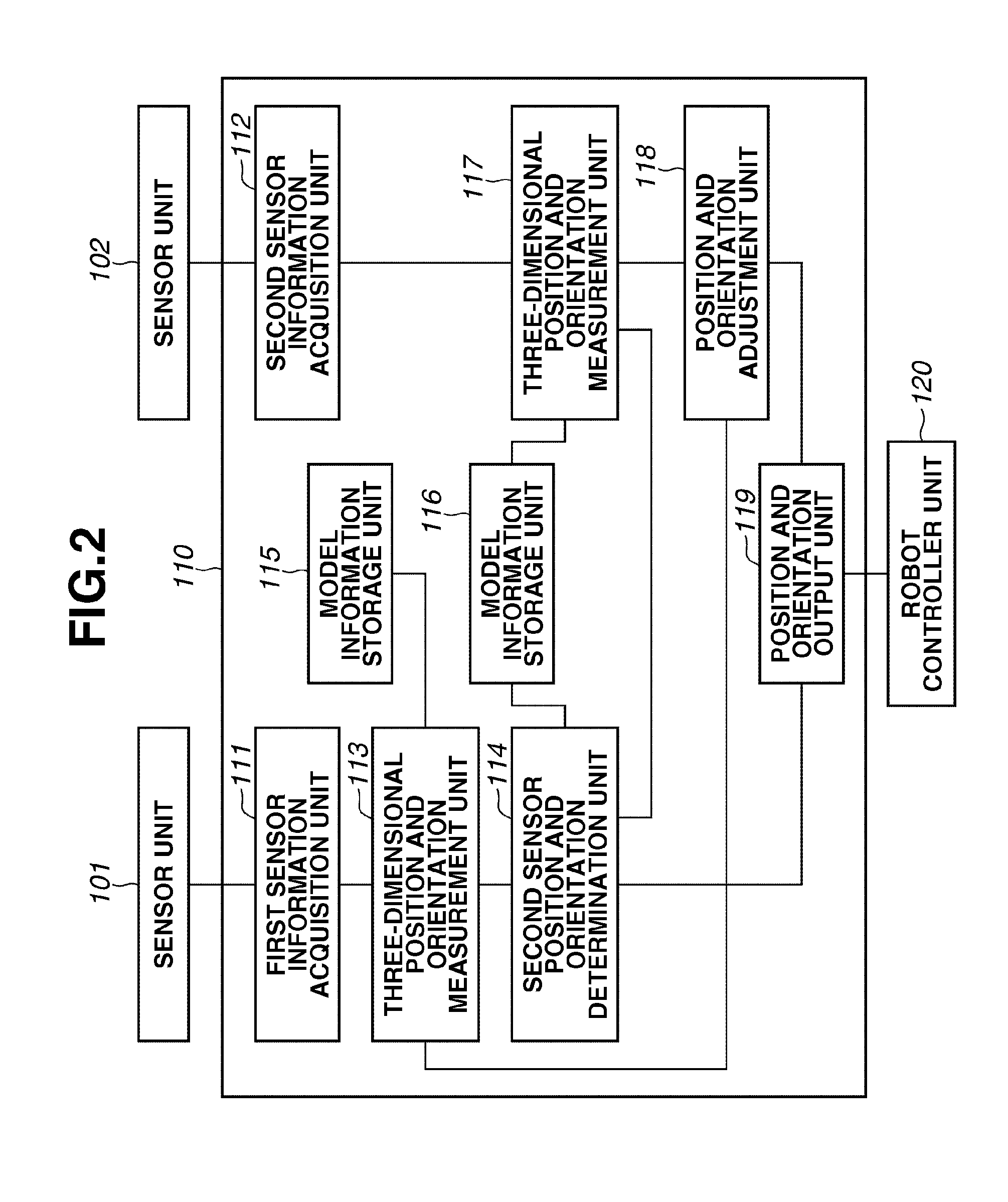
An apparatus is provided with a first sensor unit that obtains two-dimensional information or three-dimensional information about a target object with a first position and orientation, a second sensor unit that obtains the two-dimensional information about the target object, a three-dimensional position and orientation measurement unit that measures three-dimensional position and orientation of the target object based on the information obtained by the first sensor unit, a second sensor position and orientation determination unit that calculates second position and orientation based on a measurement result with the three-dimensional position and orientation measurement unit and model information about the target object, and a three-dimensional position and orientation measurement unit that measures the three-dimensional position and orientation of the target object based on the information obtained by the second sensor unit with the second position and orientation and the model information about the target object.

Description

BACKGROUND OF THE INVENTION[0001]1. Field of the Invention[0002]The present invention relates to an information processing system for controlling a movable unit including a movable portion capable of changing an position and a orientation and a method, a program, and a computer-readable storage medium therefor.[0003]2. Description of the Related Art[0004]With recent progress in robot technology, robots are beginning to perform complicated tasks, instead of people, which had been performed by people in the past such as assembling of industrial products. Such robot performs an assembling process by picking up a component using an end effector such as a hand.[0005]In the past, components which are to be picked up are supplied by utilizing an apparatus, which is called a parts feeder, for supplying components by arranging each of the components one by one or by stacking components in a pallet (a box) in various orientations. When a part feeder is used, each of the components is supplied...

Claims


Application Information

Patent Timeline
Patent Type & Authority Applications(United States)
IPC IPC(8): G05D3/00
CPCG05D3/00B25J9/1697G05B2219/37567G05B2219/40604
Inventor KOBAYASHI, KAZUHIKOSUZUKI, MASAHIROUCHIYAMA, SHINJI
Owner CANON KK
Learn More