Display control device, method, and program
a control device and display technology, applied in the field of display control devices, can solve the problems of increasing the number of operation buttons of the remote controller and the complexity of operation, and achieve the effect of improving the operability of users
Active Publication Date: 2014-03-06
SONY SEMICON SOLUTIONS CORP
View PDF14 Cites 29 Cited by
- Summary
- Abstract
- Description
- Claims
- Application Information
AI Technical Summary
Benefits of technology
The patent text describes a way to make it easier for users to interact with a free-cursor type user interface. The goal is to improve user operability.
Problems solved by technology
In a recent digital television set, since displayed information or operation items are increased in addition to the broadcast pictures, the number of operation buttons of a remote controller increases and operation becomes complicated.
Method used
View moreImage
Smart ImageViewing Examples
Examples
first embodiment (
1. First embodiment (a configuration providing a free-cursor type user interface)
second embodiment (
2. Second embodiment (an example specifying an operator from plural users)
third embodiment (
3. Third embodiment (an example of an application to a camera system which performs video communication)
Login to View More PUM
 Abstract
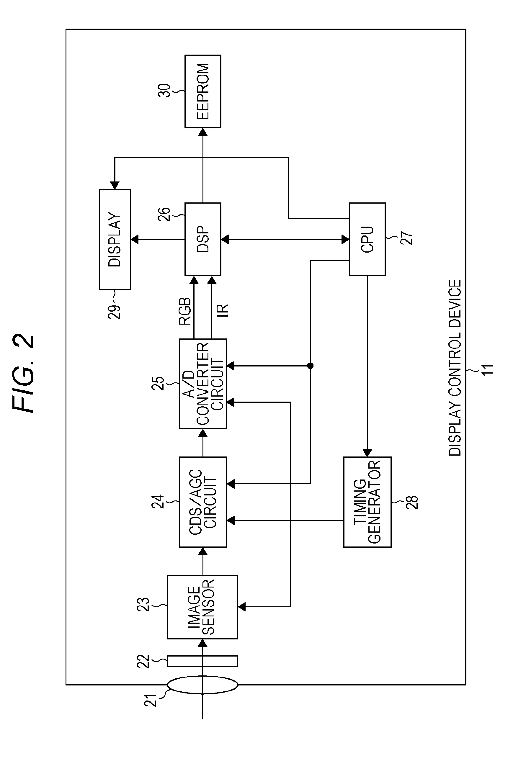
The present technique relates to a display control device, a method, and a program that can improve user's operability of a free-cursor type user interface.An imaging unit outputs an RGB image based on a pixel signal corresponding to a visible light among light input through a lens and an IR image based on a pixel signal corresponding to an infrared light among light input through the lens. An ROI set unit sets a movement area of an infrared light source in the IR image based on the RGB image, and a display control unit controls a cursor movement amount on a display unit according to movement of the infrared light source in the movement area. The present technique can be applied to a television set that monitors a viewing condition of a viewer, for example.
Description
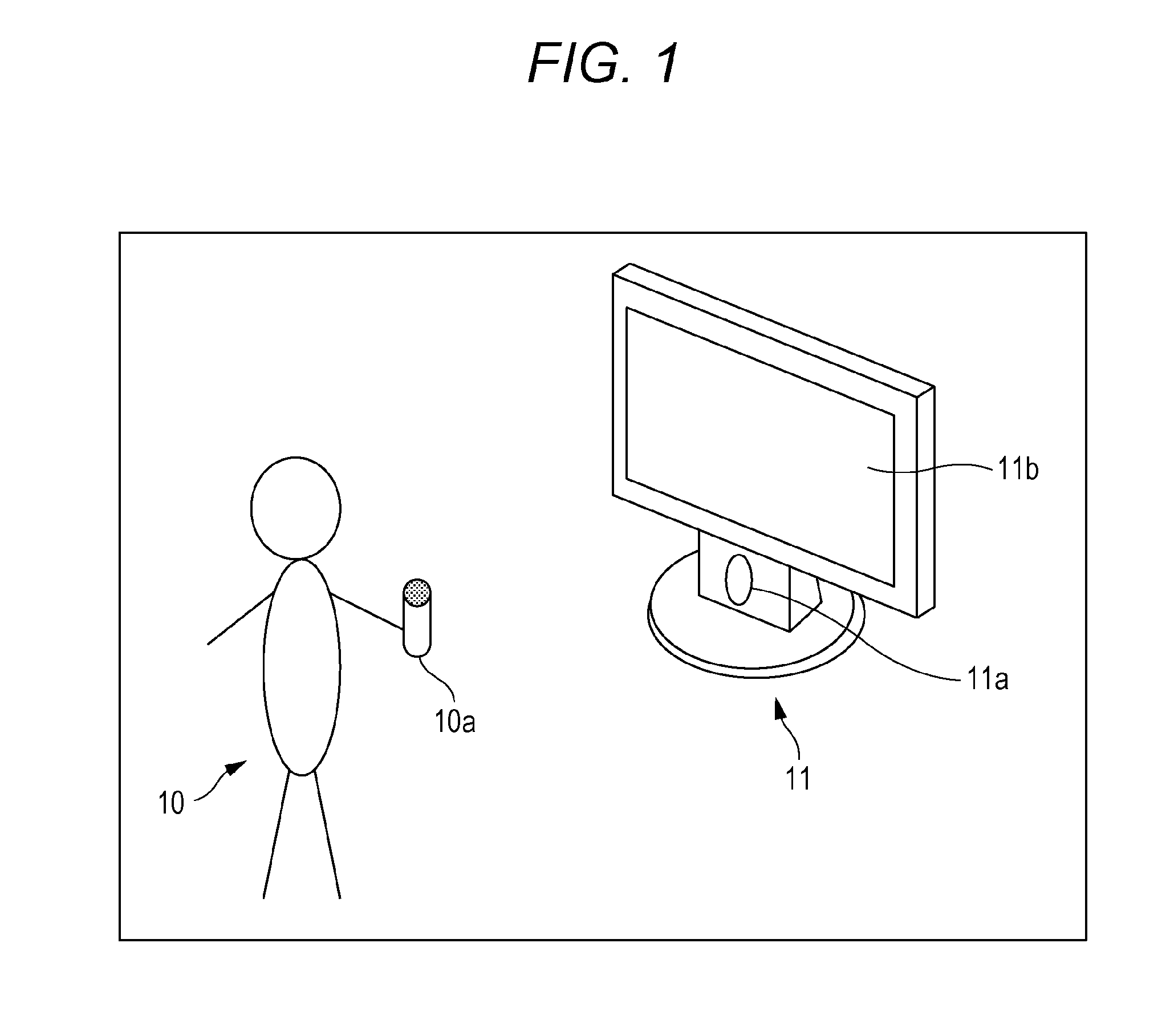
TECHNICAL FIELD[0001]The present technique relates to a display control device, a method, and a program, more particularly, a display control device, a method and a program which can improve user's portability of a free-cursor type user interface.BACKGROUND ART[0002]In a recent digital television set, since displayed information or operation items are increased in addition to the broadcast pictures, the number of operation buttons of a remote controller increases and operation becomes complicated.[0003]In a view of this problem, a free-cursor type user interface has been proposed, in which an infrared-transparent filter that blocks a visible light and transmits a near-infrared light is provided at a lens part of a digital camera to take an image of a near-infrared light spot of the remote controller of the operator and to allow a selection of menu icons or the like on the display by moving a cursor on the display in conjunction with the movement of the operator's hand (see Patent Do...
Claims
Login to View More Application Information
Patent Timeline
 IPC IPC(8): G06F3/03G06F3/033G06F3/0346G06F3/038
CPCG06F3/0304G06F3/038G06T2207/10016G06T2207/10024G06T2207/10048G06T2207/30196G06T2207/30204G06T3/40H04N21/42221H04N21/4223H04N21/44008G06T7/246
Inventor OZAWA, KENIWASAKI, MASANORIMOGI, HIDEAKI
Owner SONY SEMICON SOLUTIONS CORP
Features
- R&D
- Intellectual Property
- Life Sciences
- Materials
- Tech Scout
- Unparalleled Data Quality
- Higher Quality Content
- 60% Fewer Hallucinations
Learn More Browse by: Latest US Patents, China's latest patents, Technical Efficacy Thesaurus, Application Domain, Technology Topic, Popular Technical Reports.
© 2025 PatSnap. All rights reserved.Legal|Privacy policy|Modern Slavery Act Transparency Statement|Sitemap|About US| Contact US: help@patsnap.com


