
Touch panel

a technology of touch panel and keyboard, which is applied in the field of touch panel, can solve the problems of deteriorating visibility, difficult to efficiently operate a product using only the keyboard and the mouse currently serving as the input device, etc., and achieve the effect of preventing a moire phenomenon and improving visibility

Inactive Publication Date: 2014-02-27
SAMSUNG ELECTRO MECHANICS CO LTD
View PDF6 Cites 42 Cited by
  • Summary
  • Abstract
  • Description
  • Claims
  • Application Information

AI Technical Summary

Benefits of technology

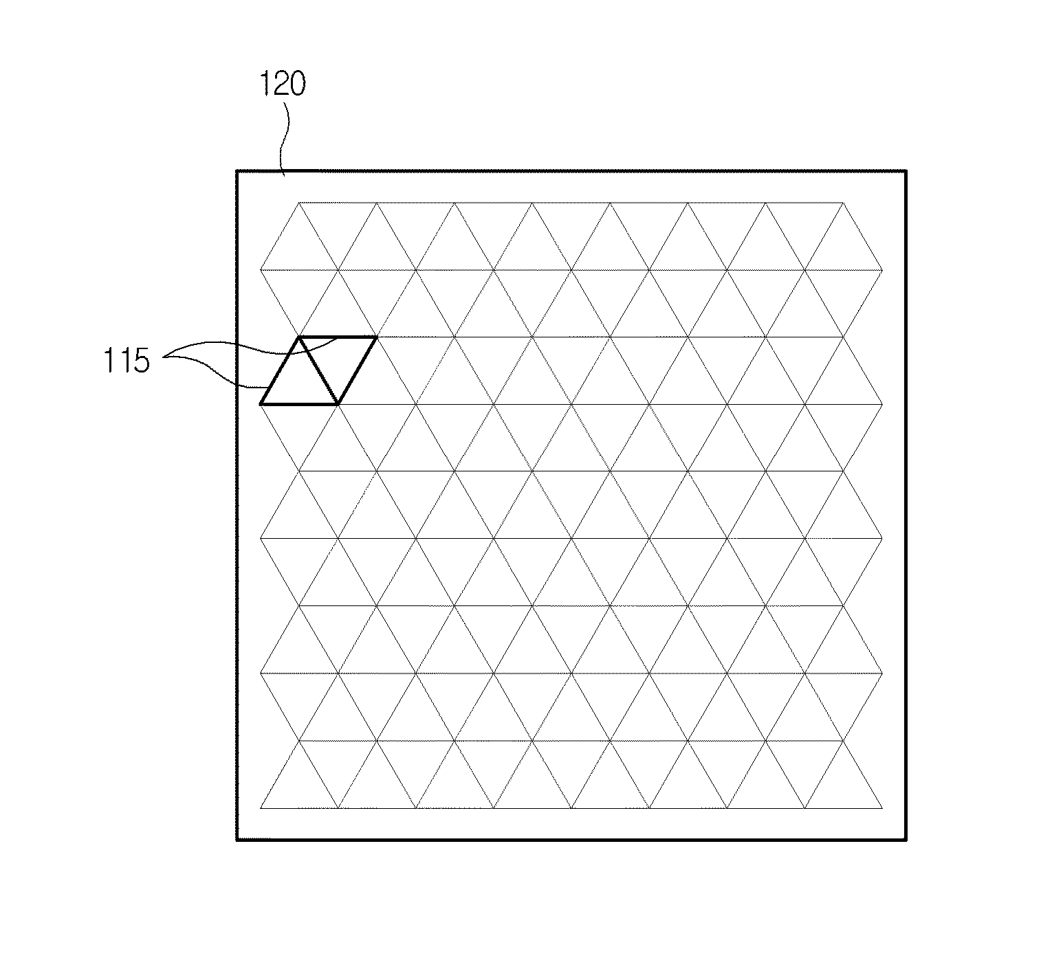
The present invention is a touch panel that tries to prevent the Moire phenomenon and improve visibility. It does this by creating imaginary lattices made of the same polygons, randomly generating predetermined points in those polygons, and connecting the predetermined points to the vertices (seeing points) of the polygons. This results in a more organized and less noisy image, making it easier for users to see and interact with the touch panel.

Problems solved by technology

However, according to rapid advancement of an information-oriented society, since use of computers has increasingly expanded, it is difficult to efficiently operate a product using only the keyboard and the mouse currently serving as the input device.
However, when the electrode pattern of the touch panel is formed in the mesh structure having regular and constant intervals, period characteristics of the electrode pattern of the touch panel and a black matrix pattern of a color filter included in an image display device (a liquid crystal display (LCD), or the like) are overlapped with each other, such that a Moire phenomenon is generated, thereby deteriorating visibility.

Method used


Image

  • Touch panel
  • Touch panel
  • Touch panel

Examples


Embodiment Construction

[0036]The objects, features and advantages of the present invention will be more clearly understood from the following detailed description of the preferred embodiments taken in conjunction with the accompanying drawings. Throughout the accompanying drawings, the same reference numerals are used to designate the same or similar components, and redundant descriptions thereof are omitted. Further, in the following description, the terms “first”, “second”, “one side”, “the other side” and the like are used to differentiate a certain component from other components, but the configuration of such components should not be construed to be limited by the terms. Further, in the description of the present invention, when it is determined that the detailed description of the related art would obscure the gist of the present invention, the description thereof will be omitted.

[0037]Hereinafter, preferred embodiments of the present invention will be described in detail with reference to the attac...


PUM


Abstract

Disclosed herein is a touch panel including an electrode pattern formed by forming imaginary lattices configured of same polygons as each other, randomly generating predetermined points in the polygons, and connecting the predetermined points and vertexes of the polygons to each other. The electrode pattern is irregularly formed, thereby making it possible to prevent a Moire phenomenon and improve visibility.

Description

CROSS REFERENCE TO RELATED APPLICATION[0001]This application claims the benefit of Korean Patent Application No. 10-2012-0092599, filed on Aug. 23, 2012, entitled “Touch Panel”, which is hereby incorporated by reference in its entirety into this application.BACKGROUND OF THE INVENTION[0002]1. Technical Field[0003]The present invention relates to a touch panel.[0004]2. Description of the Related Art[0005]In accordance with the growth of computers using a digital technology, devices assisting computers have also been developed, and personal computers, portable transmitters and other personal information processors execute processing of text and graphics using a variety of input devices such as a keyboard and a mouse.[0006]However, according to rapid advancement of an information-oriented society, since use of computers has increasingly expanded, it is difficult to efficiently operate a product using only the keyboard and the mouse currently serving as the input device. Therefore, nece...

Claims


Application Information

Patent Timeline
Patent Type & Authority Applications(United States)
IPC IPC(8): G06F3/041
CPCG06F3/041G06F3/0412G06F3/044G06F3/046G06F3/0448
Inventor HAN, SEUNG HEONKIM, HEE SOONOH, JUNG EUN
Owner SAMSUNG ELECTRO MECHANICS CO LTD
Learn More