
Variable Weight Hammer Useful as Exercise Apparatus

a technology of hammer and weight, which is applied in the field of exercise equipment, can solve the problems of falling out of favor and devices that require a lot of adaptation or specialty materials

Active Publication Date: 2014-02-20
MANHAMMER COMPANY
View PDF2 Cites 22 Cited by
  • Summary
  • Abstract
  • Description
  • Claims
  • Application Information

AI Technical Summary

Benefits of technology

The patent text describes an apparatus for training weight lifting. The apparatus has two bars that can be joined together using a collar. The second bar section has a rough surface to prevent weights from slipping on it. The second bar section is also threaded to attach weights to it. The user can grip the apparatus with their hands to stabilize the weight load and provide counter strength training. The technical effect of this invention is a versatile and effective tool for weight lifting training.

Problems solved by technology

However, it fell out of favor and is enjoying a revival of sorts based on new exercise trends and equipment.
While new devices are developing for safely taking advantage of traditional physical labor movements for upper body, core, back and all-around physical strength training, such devices require a lot of adaptation or specialty materials.

Method used


Image

  • Variable Weight Hammer Useful as Exercise Apparatus
  • Variable Weight Hammer Useful as Exercise Apparatus
  • Variable Weight Hammer Useful as Exercise Apparatus

Examples


embodiment 100

[0056]As shown in FIGS. 5 to 9, a further embodiment of the apparatus herein is shown, and is generally referred to herein as apparatus 200. Reference numbers in this embodiment are analogous to those of embodiment 100, except to the extent noted here. The bar body 202 of this embodiment extends from a gripping end 206 to the top surface 218 of the hammer head 214. The first bar section 208 of the bar body 202 is generally the same and may be formed analogously to that of the first apparatus 100 shown in FIG. 1. However, the second bar section 216 in this embodiment has an outer surface 244 having threads 246 configured to receive mating threads 248 on an interior surface 250 of a screw-on weight retention collar 252.

[0057]In the embodiment of FIG. 6, the hammer head 214 is preferably configured to be more elongated and so as to be generally square in cross section taken in a transverse direction across the hammer head. Additional cross-sectional shapes can also be used, however, th...

embodiment 400

[0061]A further embodiment of the apparatus, embodiment 400, is shown in FIG. 5A. It is similar to that of FIG. 1, and analogous reference numbers refer to analogous parts, however, the hammer head 414 is more disc-shaped. The hammer head 414 has a striking surface 438 that is curved as the cross section of the head 414 measured in the transverse direction is generally circular and the cross section of the head 414 measured in the longitudinal direction is generally rectangular. Thus the top surface 418 and weight-facing bottom surface 254 of the head 414 appear circular as well. The disc head 414 may have a preferred width (thickness) of about 1 in. to about 4 in., preferably about 2 in. to about 3 in. and a preferred diameter of about 7 to about 10 in., preferably about 8 in. to about 9 in.

[0062]The embodiment shown in FIG. 5A also has a second bar section 416 has a smooth exterior surface 444. Optional holes 459 may be provided for receiving weight retention pins as are known in ...


PUM


Abstract

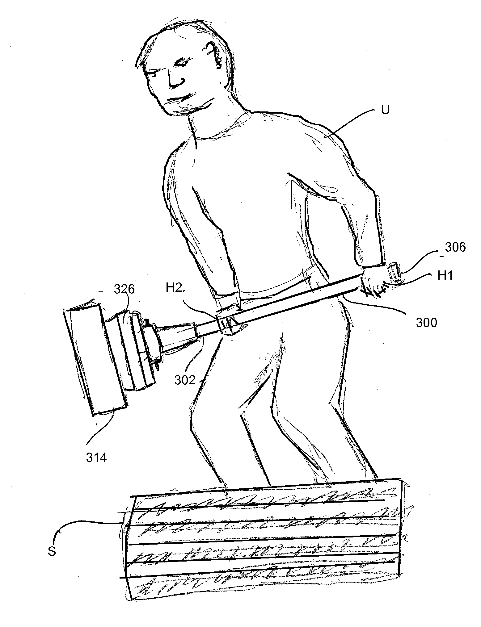
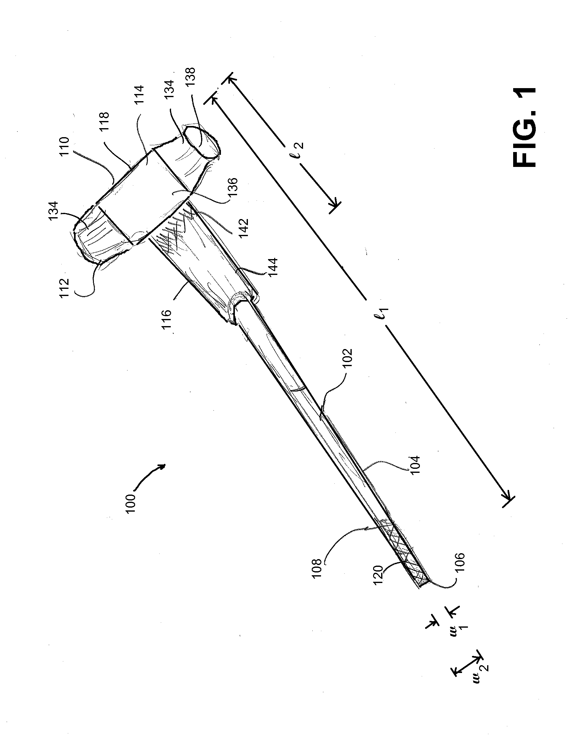
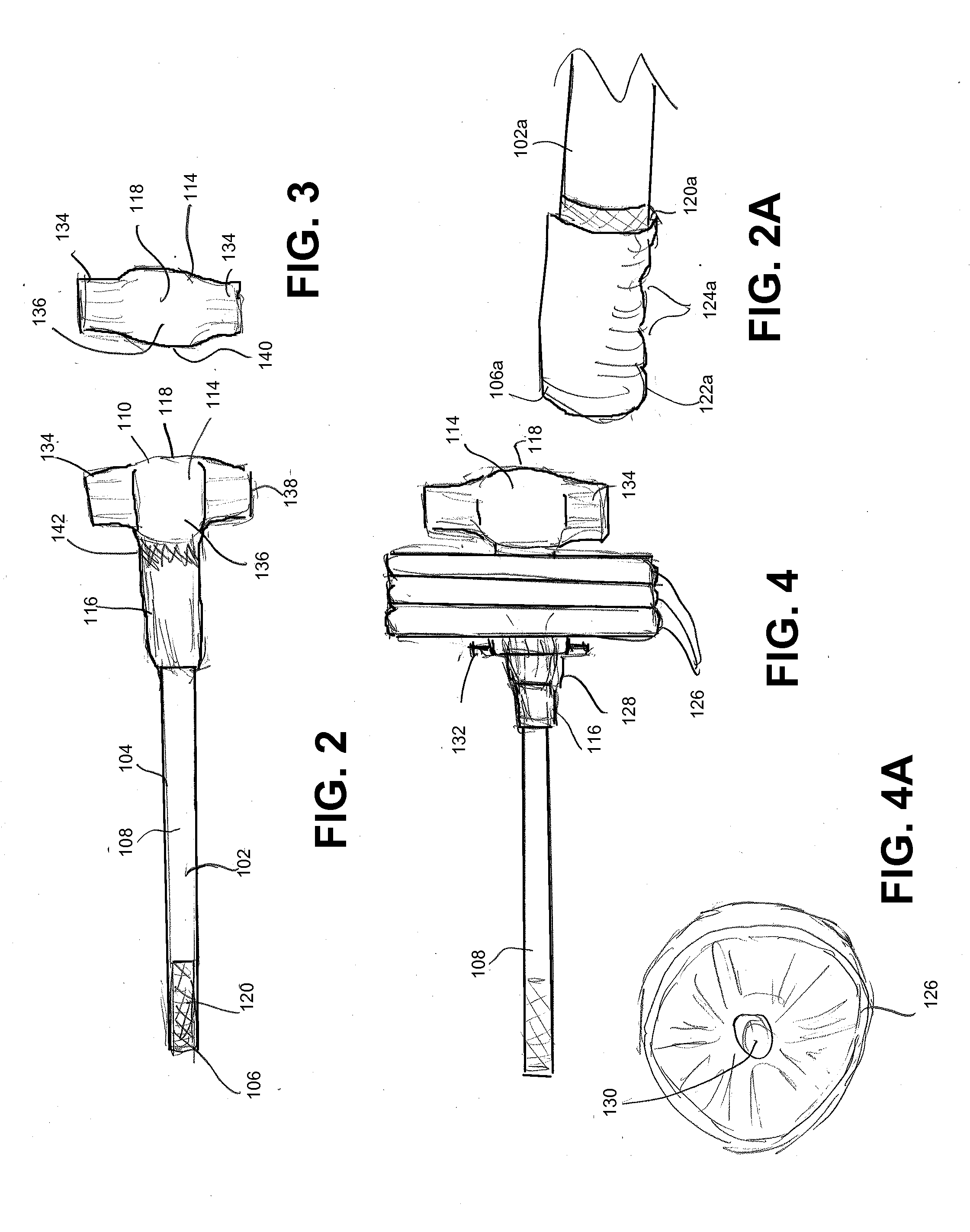
An apparatus and methods of using the apparatus are included herein which apparatus includes a longitudinally extending bar body having an exterior surface and extending from a gripping end on a first bar section thereof to a second end comprising a hammer portion; wherein the hammer portion comprises a hammer head and the bar body comprises a second bar section extending from the hammer head at least partially along the bar body configured for receiving at least one weight positioned adjacent the hammer head. The apparatus is useful, for example, as a strength training fitness apparatus, a construction or demolition tool capable of supporting variable weight, and / or a strength training device for training workers.

Description

CROSS-REFERENCE TO RELATED APPLICATIONS[0001]This application claims the benefit under 35 U.S.C. §119(e) to U.S. Provisional Patent Application No. 61 / 682,752, filed Aug. 13, 2013, the entire disclosure of which is incorporated herein by reference.BACKGROUND OF THE INVENTION[0002]1. Field of the Invention[0003]The invention relates to the fields of exercise equipment, specifically equipment for strength and core training based on hammer motion exercise, and hand held devices such as tools, which may be used other construction or building purposes, such as demolition work.[0004]2. Description of Related Art[0005]Weight-lifting and strength training for improvement to upper body, core and overall muscular groups is increasingly popular. The desire to build and sculpt the human musculature for overall strength and well-being is a focus of a large amount of specialty exercise equipment, both electronic weight training machines, resistance machines, and traditional free weights. Free wei...

Claims


Application Information

Patent Timeline
Patent Type & Authority Applications(United States)
IPC IPC(8): A63B15/00
CPCA63B15/00A63B21/072A63B21/0728A63B21/075A63B21/4035A63B23/03525A63B2225/09
Inventor WALKER, JOSEPH
Owner MANHAMMER COMPANY
Learn More