
Bolometric detector of an electromagnetic radiation in the terahertz range and array detection device comprising such detectors

a detector and electromagnetic radiation technology, applied in radiation pyrometry, instruments, material analysis, etc., can solve the problems of inability to capture all electromagnetic power, inability to receive electromagnetic power by a single antenna, and inability to efficiently compensate.

Active Publication Date: 2014-02-20
COMMISSARIAT A LENERGIE ATOMIQUE ET AUX ENERGIES ALTERNATIVES
View PDF10 Cites 8 Cited by
  • Summary
  • Abstract
  • Description
  • Claims
  • Application Information

AI Technical Summary

Benefits of technology

The present invention aims to provide a circuit for a terahertz bolometric detector that efficiently compensates for non-useful signals generated by sensitive bolometers. The detector comprises a reference bolometer made insensitive to the terahertz radiation to be detected. The reference bolometer is made insensitive to the terahertz radiation by forming a destructive interference fringe. The use of resistive loads in the reference bolometer is minimized by accepting possible resonances resulting from uncertainties of manufacturing technology. The reference bolometer also includes a microbridge with a metal film and fins arranged opposite to the first antenna, which performs an impedance matching with the first antenna. The efficient use of the reference bolometer in the detector allows for the efficient compensation of non-useful signals, resulting in improved detection efficiency.

Problems solved by technology

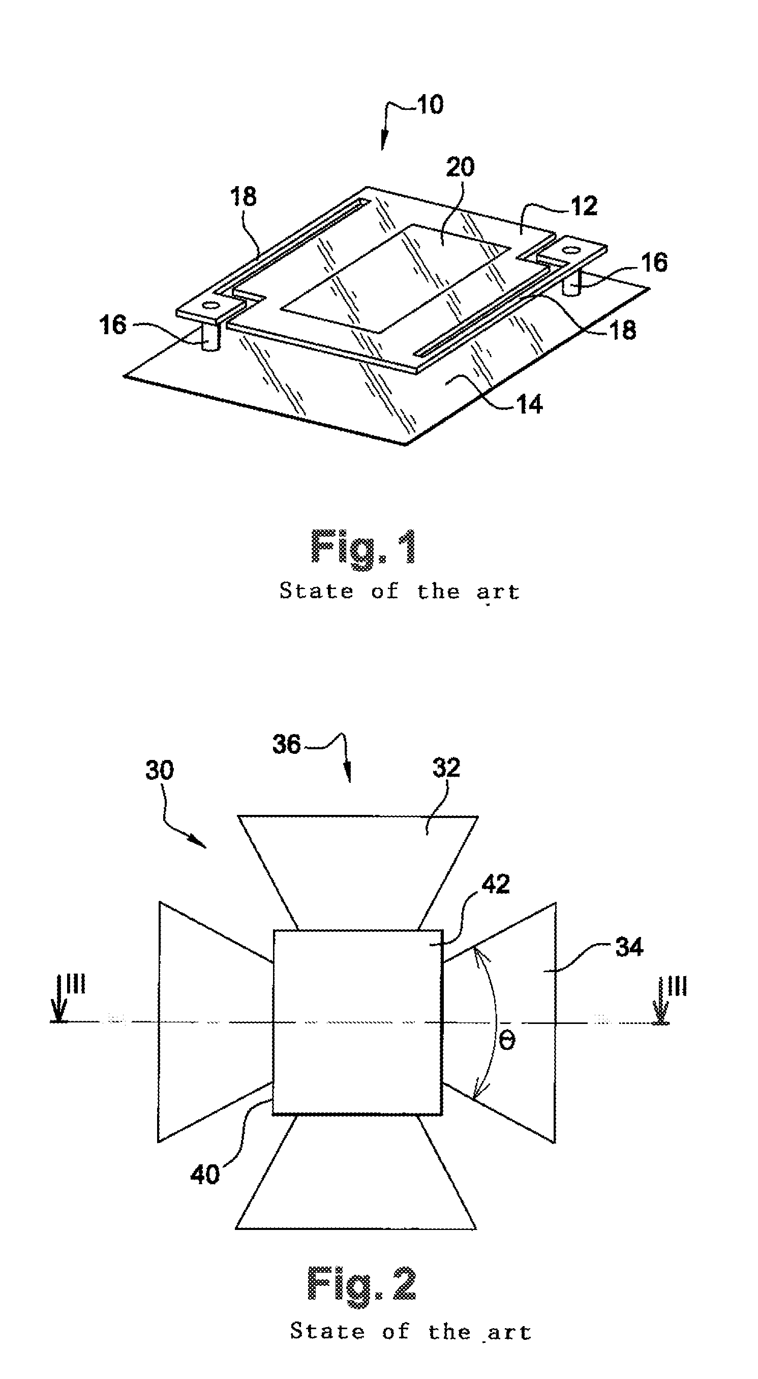
However, for such dimensions, the thermal mass, the mechanical hold, and the radiative losses of the membrane are such a problem that they eventually adversely affect the detector efficiency.
Further, in most cases, the incident electromagnetic radiation is not polarized, so that its reception by a single antenna does not enable to capture all of the electromagnetic power.
While the fact of suspending the thermometric element above the substrate enables it to undergo an electric resistance variation under the effect of the incident radiation, such a variation however remains minute.
The most part of the electric resistance of thermometric material layer 20 being set by elements unrelated to the observed scene, in the absence of specific measure, the detector read dynamics is thus very limited, which makes such a detector very difficult to use.
This type of structure, optimal from the common mode viewpoint, is however difficult and expensive to manufacture.
While the skimming structure just described provides satisfactory results in infrared detection, its application to terahertz detection is not satisfactory.
Indeed, only the non-useful part of the currents flowing through the sensitive bolometers is to be reproduced, and thus the useful part of said currents, which correspond, in this application, to the infrared radiation to be detected are not to be compensated for.
However, in the context of a terahertz detection, infrared radiation becomes a disturbing element having a non-negligible influence due to its high intensity, infrared radiation most often having an intensity greater by several orders of magnitude than the intensity of terahertz radiation.
However, if a skimming structure similar to that of an infrared detector, that is, desensitized to the radiation originating from the scene, is provided in a terahertz detector, the skimming structure is also desensitized to infrared radiation, so that it does not reproduce the non-useful part corresponding to this radiation.
Since it is not reproduced, this non-useful part is thus not compensated for in the current flowing through the sensitive bolometers.
Further, a skimming structure which is not desensitized to the radiation originating from the scene cannot be envisaged, since such a structure would reproduce the useful part corresponding to terahertz radiation, which useful part would be compensated for in the current of the sensitive bolometers.

Method used


Image

  • Bolometric detector of an electromagnetic radiation in the terahertz range and array detection device comprising such detectors
  • Bolometric detector of an electromagnetic radiation in the terahertz range and array detection device comprising such detectors
  • Bolometric detector of an electromagnetic radiation in the terahertz range and array detection device comprising such detectors

Examples


first embodiment

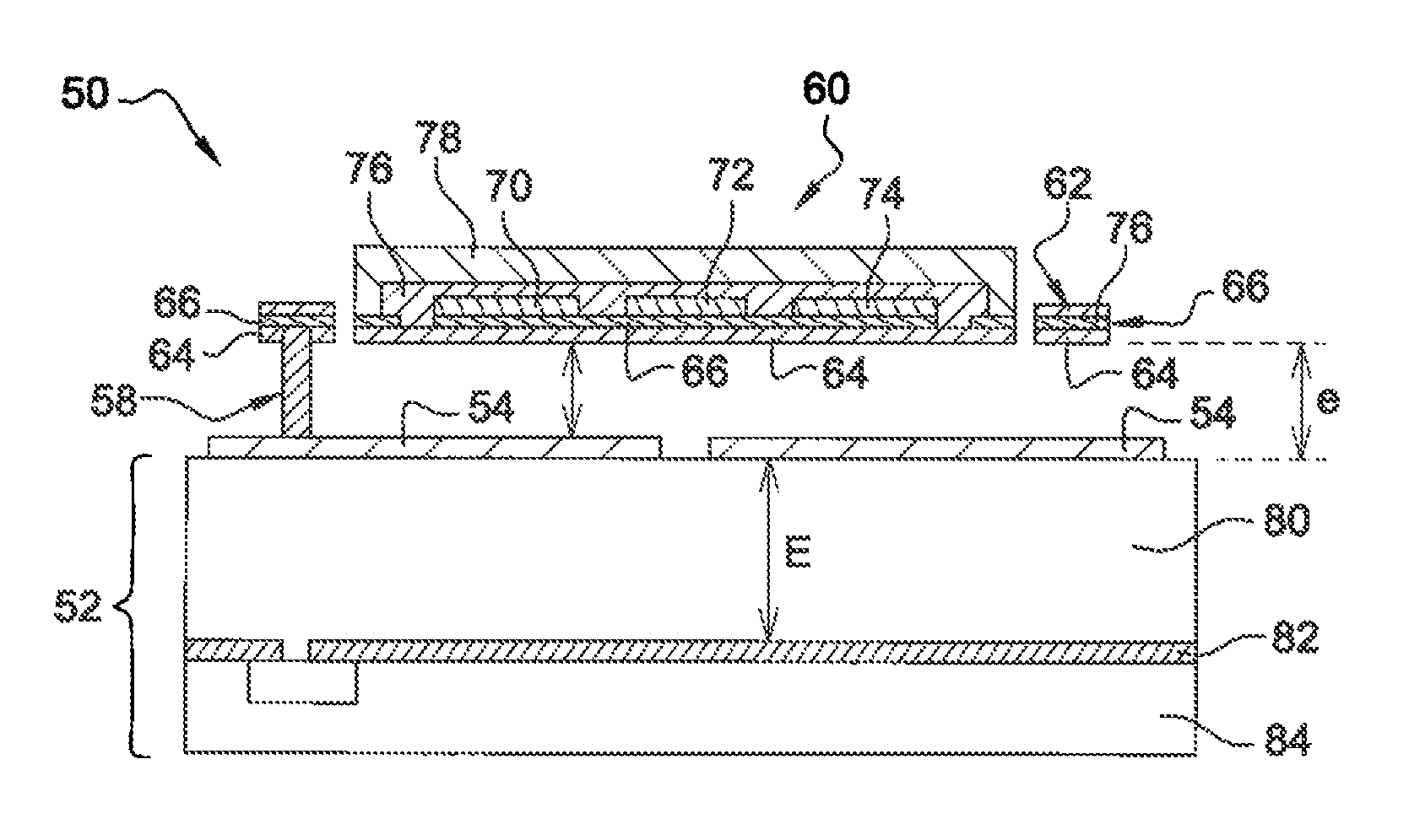
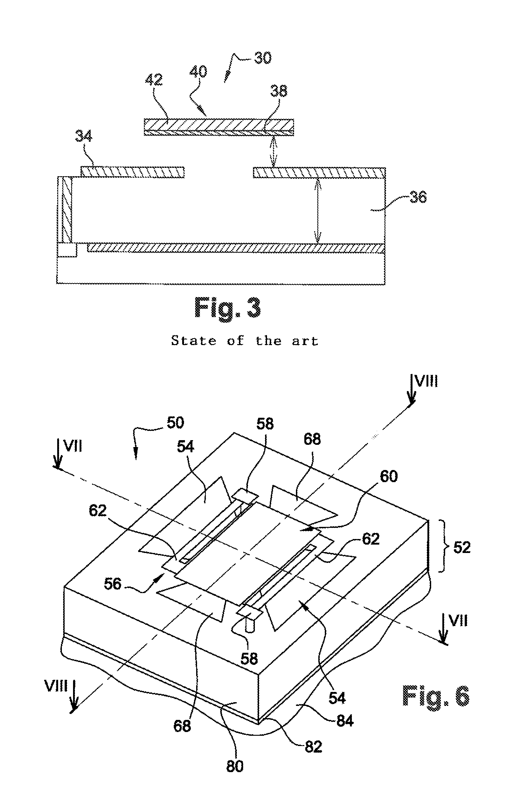
[0107]For this purpose, in a first embodiment illustrated in FIGS. 10 to 12, a reference bolometer 120 according to the invention is identical to sensitive bolometer 50 illustrated in FIGS. 6 to 8, but for the fact that:[0108]first antenna 54 of sensitive bolometer 50 is replaced with a layer 122 reflecting with a 180° phase shift the radiation incident on microbridge 56 and crossing it, advantageously a metal layer, deposited on insulating substrate 52 under and around microbridge 56. Advantageously, the layer is made of the same material as antenna 54 and has a thickness preferably identical to that of antenna 54 of the sensitive bolometer. The dimensions of metal layer 122 are selected to be at least equal to the projected surface area of microbridge 56;[0109]distance e between metal layer 122 and microbridge 56 which places microbridge 56 of reference bolometer 120 in a destructive interference fringe between the radiation incident on layer 122 and the radiation reflected with a...

second embodiment

[0111] the reference bolometer differs from reference bolometer 120 in that resistive load 66 is omitted.

[0112]According to a third embodiment, the reference bolometer differs from reference bolometer 120 in that the resistive load is shorted. The absence or the shorting of resistive load 66 thus enables to reject possible resonance resulting from a patch antenna behavior, outside of the active detector operating range, while providing substantially identical results in terms of infrared absorption than the first embodiment.

[0113]The embodiments just described have the advantage of providing a reference bolometer having a very small number of differences with respect to the sensitive bolometer, which especially enables to manufacture these bolometers jointly by means of the same manufacturing techniques. Of course, the reference bolometer may differ by greater proportions from the sensitive bolometer. For example, the reference bolometer may advantageously have no resonant cavity 80...


PUM


Abstract

A terahertz detection device comprises at least one terahertz antenna, a detection microbridge suspended above a substrate comprising a resistive load coupled to the antenna and a resistive bolometric clement coupled to the resistive load, a bias circuit for biasing the bolometric element. The device further comprises a skimming microbridge suspended above the substrate, comprising a resistive bolometric element, and substantially identical to the detection microbridge, a reflective metal layer opposite to the skimming microbridge to obtain a destructive interference at the level of the skimming microbridge for a terahertz wavelength, a bias circuit to electrically bias the bolometric element of the skimming microbridge and a read circuit for measuring a difference between the electric signals of the microbridges.

Description

FIELD OF THE INVENTION[0001]The present disclosure relates to the field of bolometric detectors with antennas, intended for the detection of an electromagnetic radiation in the terahertz range.[0002]For a detection in the terahertz range, that is, in the frequency range comprised between approximately 100 gigahertz and approximately 10 terahertz, non-limiting applications of the invention relate to:[0003]medical diagnosis, for which the detection in the terahertz ranges provides access to anatomical structure details and the chemical reactions occurring therein, which are neither provided by X rays, nor by ultrasounds;[0004]the military field and air security, with, for example, the forming of anti-stealth radars or of high-resolution radars allowing a discrimination;[0005]the study and the detection of air pollution, submillimetric wave observation effectively providing important information relative to air chemistry and thus allowing an unequaled follow-up of air pollutants, such ...

Claims


Application Information

Patent Timeline
IPC IPC(8): G01J5/24
CPCG01J5/24G01J5/0837G01J5/22
Inventor OUVRIER-BUFFET, JEAN-LOUISMEILHAN, JEROMENGUYEN, DUY THONGSIMOENS, FRANCOIS
Owner COMMISSARIAT A LENERGIE ATOMIQUE ET AUX ENERGIES ALTERNATIVES
Learn More