
Modular solar systems facilitating rapid assembly

Inactive Publication Date: 2014-02-20
SAHAR G N
View PDF8 Cites 14 Cited by
  • Summary
  • Abstract
  • Description
  • Claims
  • Application Information

AI Technical Summary

Benefits of technology

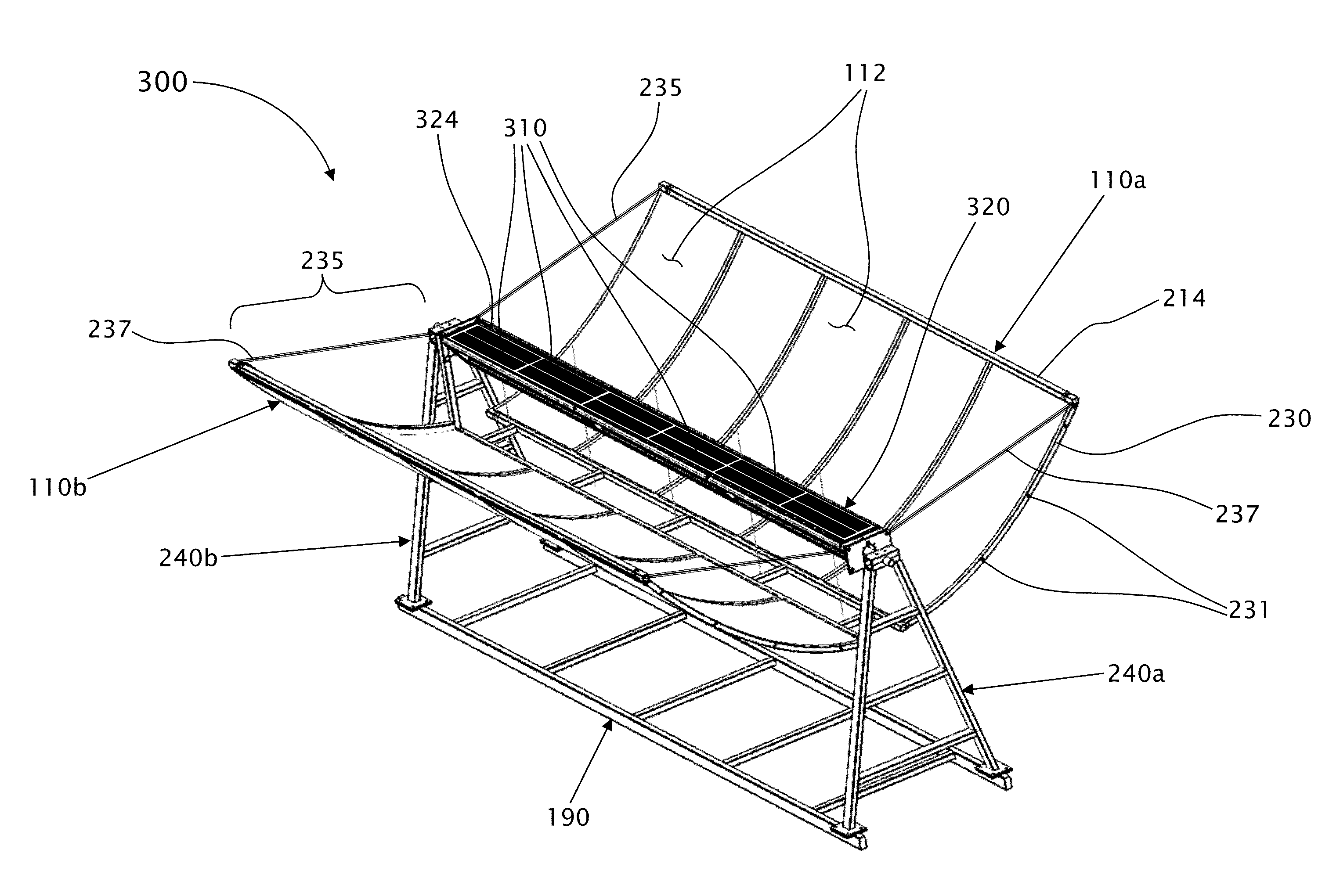
The present invention is a system for concentrating solar radiation to provide heat and power. The invention aims to avoid energy loss due to reflections from a low incidence angle of the energy on the receiver. The invention achieves this by spreading the radiation over only a portion of the receiver surface without over-concentrating it in one spot. This is achieved using a parabolic reflector that places its energy on a different spot of the receiver and whose incidence is normal. The technical effect of the invention is improved efficiency and reduced energy loss.

Problems solved by technology

One unappreciated problem of concentrating solar energy is the reflection of incoming energy off of the receiver element.
When the incidence angle is low enough, the surface acts as a reflector rather than an absorber and the incident radiation is lost.
These same phenomena cause mirages.
On the other hand, if the energy is concentrated in too small an area on the receiver, it will heat up giving a large temperature and large temperature gradient, which then loses heat by radiation, convection, and conduction to the surroundings.

Method used


Image

  • Modular solar systems facilitating rapid assembly
  • Modular solar systems facilitating rapid assembly
  • Modular solar systems facilitating rapid assembly

Examples


Embodiment Construction

[0121]Before explaining embodiments of the invention in detail, it is to be understood that the invention is not limited in its application to the details of construction and the arrangement of the components set forth in the host description or illustrated in the drawings. Various modifications, however, will remain apparent to those skilled in the art.

[0122]An embodiment is an example or implementation of the inventions. The various appearances of “one embodiment,”“an embodiment” or “some embodiments” do not necessarily all refer to the same embodiments. Although various features of the invention may be described in the context of a single embodiment, the features may also be provided separately or in any suitable combination. Conversely, although the invention may be described herein in the context of separate embodiments for clarity, the invention may also be implemented in a single embodiment.

[0123]Methods of the present invention may be implemented by performing or completing ...


PUM

PropertyMeasurementUnit
Temperatureaaaaaaaaaa
Weightaaaaaaaaaa
Angleaaaaaaaaaa

Abstract

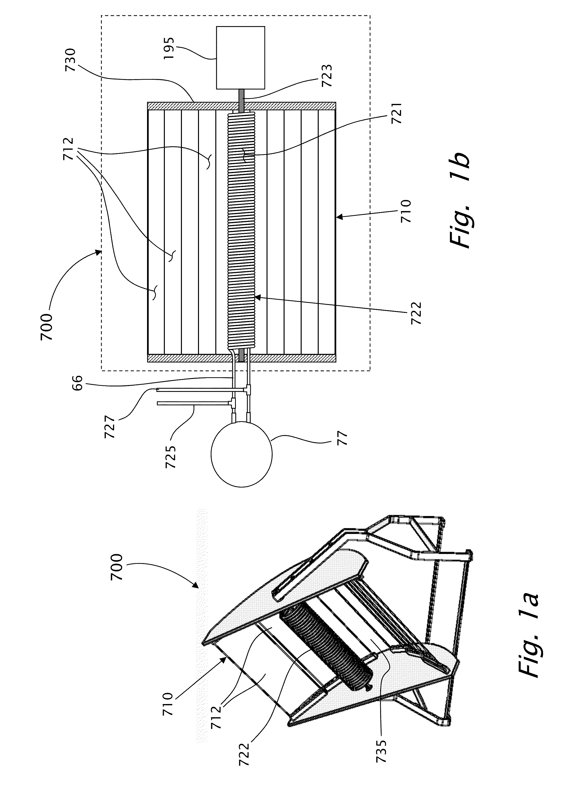
A solar system for collecting solar energy, adapted to be rapidly assembled on site. The modular solar system includes a solar energy collector-assembly, having two wings of collectors, arranged in at least one row. The modular solar system further includes an energy-receiving-module, having a receiver unit, adapted to absorb the solar energy, a shaft, a support structure, a stand, disposed on rigid surface, a control-subsystem, a motor and a sun-following mechanism coupled to operate with the control-subsystem. The receiver unit has a diameter dr, wherein collected energy directed at the external surface of the receiver unit forms a pair of solar energy strips, each strip having a width de, such that de<dr. The solar system may be shipped by land vehicles inside one standard container, wherein each major component is light weight, and can be lifted by two workers.

Description

CROSS REFERENCE TO RELATED APPLICATION[0001]This application is a continuation in part of U.S. patent application Ser. No. 12 / 921,255, filed on Sep. 7, 2010, which is a national stage entry of PCT / IL2009 / 000283, which claims the benefit of U.S. Provisional Patent Application No. 61 / 036,086 filed Mar. 13, 2008, and of PCT application PCT / IL2012 / 050478, filed on Dec. 3, 2012, which claims the benefit of U.S. Provisional Patent Application No. 61 / 566,608 filed Dec. 3, 2011, the disclosure of all of which is incorporated by reference for all purposes as if fully set forth herein.FIELD OF THE INVENTION[0002]The present invention generally relates to solar systems, in which systems solar energy is concentrated for purposes of generating heat or power. More particularly, the present invention relates to a system for providing hot water by concentrating solar energy.[0003]The present invention further relates to methods for providing solar energy with high efficiency, performance-wise and c...

Claims


Application Information

Patent Timeline
IPC IPC(8): H01L31/058F24J2/12F24J2/24F24J2/38F24S10/40F24S10/70F24S20/20F24S23/70F24S23/71F24S23/74F24S50/20
CPCH01L31/058F24J2/24F24J2/12F24J2/38F24S10/45F24S20/20F24S23/74F24S23/82F24S25/13F24S30/425F24S50/20F24S80/60F24S2023/872F24S2025/6006H01L31/0547H02S40/44Y02E10/44Y02E10/47Y02E10/52Y02E10/60Y10T29/49355F24S10/70Y02E10/40
Inventor SCHWARTZ, ELISHAMASH, STEVENROACH, ROBERT LANDONNIR, GIORA
Owner SAHAR G N
Learn More