
Display Device, Back Plate Element and Splicing Parts of Backlight Module and Manufacturing Mold for Splicing Parts Thereof

a technology for backlight modules and display devices, which is applied in the field of liquid crystal display techniques, can solve the problems of increasing the cost of transport and storage, inconvenient manufacturing process, and increasing manufacturing costs, so as to reduce the size and volume, reduce the cost of molds, and reduce the effect of transport costs

Inactive Publication Date: 2014-02-13
SHENZHEN CHINA STAR OPTOELECTRONICS TECH CO LTD
View PDF7 Cites 4 Cited by
  • Summary
  • Abstract
  • Description
  • Claims
  • Application Information

AI Technical Summary

Benefits of technology

The present invention provides a display device, back plate element for backlight module and manufacturing mold for splicing parts. The back plate element is designed with at least two detachable splicing parts, which can be disassembled to reduce size and volume for reducing transport cost. Additionally, through adjusting the number of splicing parts, different specific shape of back plate elements can be formed, and a plurality of splicing parts can be manufactured with the same manufacturing mold. This achieves mold sharing and reduces mold cost.

Problems solved by technology

As the variety of the liquid crystal display devices increases, different molds must be prepared, which results in not only inconvenience to the manufacturing process but also an increase in manufacturing cost.
In addition, in the current manufacturing process, back plate element is usually monolithically manufactured.
Thus, the costs of transport and storage are both increased.

Method used


Image

  • Display Device, Back Plate Element and Splicing Parts of Backlight Module and Manufacturing Mold for Splicing Parts Thereof
  • Display Device, Back Plate Element and Splicing Parts of Backlight Module and Manufacturing Mold for Splicing Parts Thereof
  • Display Device, Back Plate Element and Splicing Parts of Backlight Module and Manufacturing Mold for Splicing Parts Thereof

Examples


first embodiment

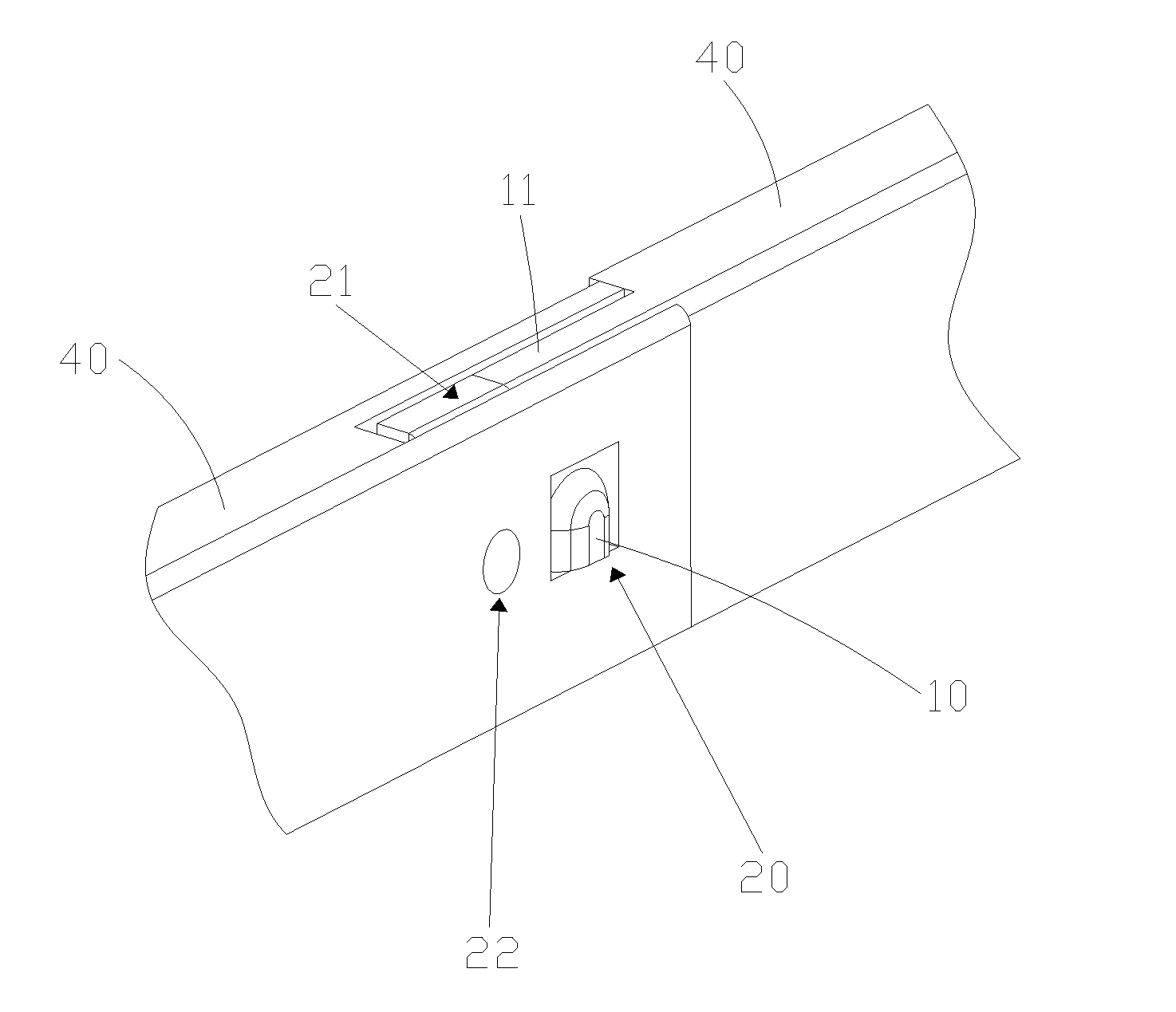
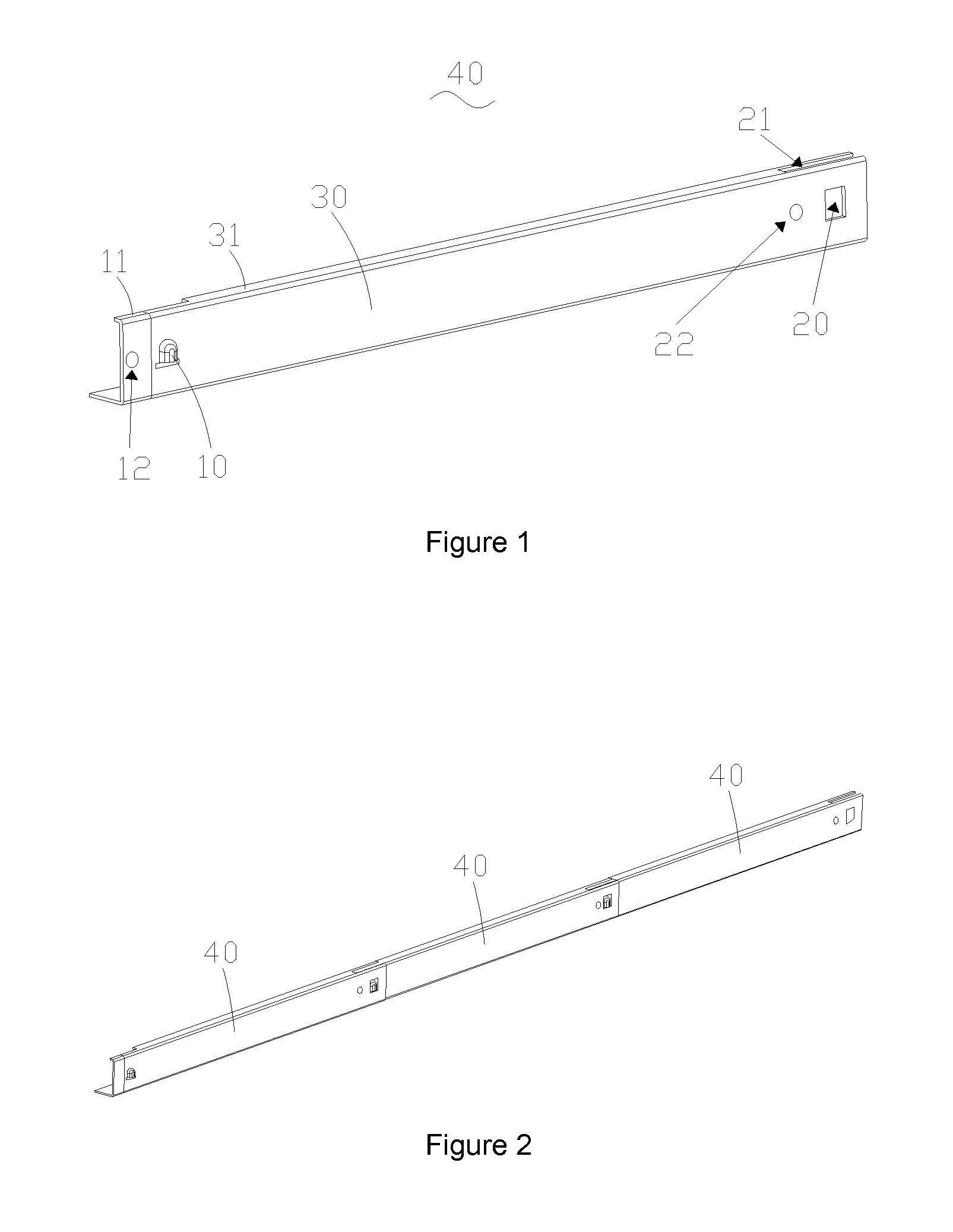
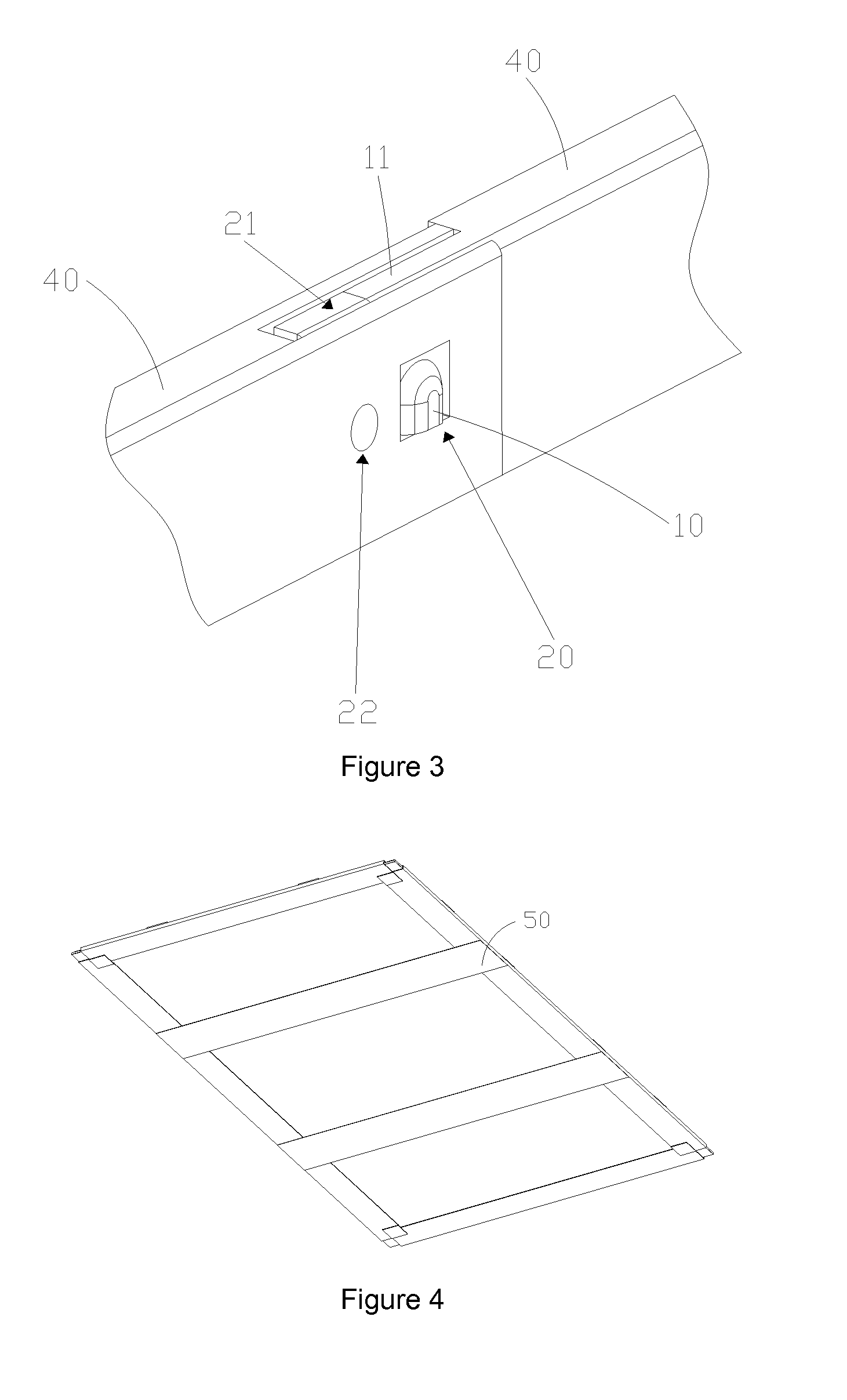
[0034]Refer to FIG. 1 and FIG. 3. In the present invention, a back plate element comprises at least two splicing parts 40 and both splicing parts 40 are disposed on a same side of an optical component. Because all splicing parts have the same structure, the following describes one splicing part for explanation.

[0035]A splicing part 40 is for connecting a splicing unit of another splicing part 40. In the instant embodiment, the length of back plate element can be adjusted through changing the number of splicing parts 40 so that the length of back plate element 40 can match the length of the side of optical component. For example, when the side length of the optical component is 20 cm and the length of splicing part 40 is 5 cm, four splicing parts 40 can be assembled into a back plate element to match the corresponding side of the optical component.

[0036]The following describes the structure of splicing part 40 and connection manner of two splicing parts 40 specifically.

[0037]Splicing...

second embodiment

[0049]the present invention provides manufacturing mold for splicing parts for manufacturing splicing parts of the previous embodiment to assemble the back plate element of the previous embodiment. The details will not be repeated here.

[0050]By the manufacturing mold of the second embodiment of the present invention, a plurality of splicing parts can be manufactured. Through adjusting the number of splicing parts, the length of back plate elements can be changed. Through mold sharing, the manufacturing mold of the second embodiment of the present invention can effectively reduce the mold cost.

[0051]The third embodiment of the present invention provides a backlight module. The backlight module comprises the back plate element of the first embodiment. The specific structure of the back plate element will not be repeated here.

[0052]The fourth embodiment of the present invention provides a display device. The display device comprises the back plate element of the first embodiment. The s...


PUM


Abstract

The present invention provides a display device, back plate element for backlight module and manufacturing mold for splicing parts. The back plate element includes at least two splicing parts and the splicing parts are disposed on the same side of optical component of backlight module. Splicing part has splicing unit for connecting another splicing part. Through adjusting the number of splicing parts, the side length of back plate elements can be adjusted to side length of optical component. The back plate element can be disassembled to reduce the transport volume. A plurality of splicing parts can be manufactured with the same manufacturing mold. As such, the present invention can achieve mold sharing and reduce mold cost.

Description

BACKGROUND OF THE INVENTION[0001]1. Field of the Invention[0002]The present invention relates to the field of liquid crystal displaying techniques, and in particular to a display device, back plate element and splicing parts of backlight module, and manufacturing mold for splicing parts thereof.[0003]2. The Related Arts[0004]Liquid crystal display device is common equipment. As widely known, the liquid crystal display device comprises backlight module and liquid crystal panel, wherein the backlight module usually comprises optical component and back plate elements.[0005]In known manufacturing techniques, specific manufacturing mold is required for making related part; therefore, different shapes or sizes of parts need to use different molds. For example, 15-inche and 19-inch liquid crystal display devices will need different back plate elements, which require different manufacturing molds to manufacture. As the variety of the liquid crystal display devices increases, different molds...

Claims


Application Information

Patent Timeline
IPC IPC(8): G09F13/04B23Q3/00
CPCG02F1/133608G09F13/04G02F1/1336
Inventor KUO, YI-CHENGHSIAO, YU-CHUNQUE, CHENGWENZHANG, PANGLINGLI, DEHUA
Owner SHENZHEN CHINA STAR OPTOELECTRONICS TECH CO LTD
Learn More