
Stabilizing Joints

a technology of stabilizing joints and spacers, applied in the field of stabilizing joints using spacers, can solve the problems of loss of water content, and affecting the ability of bone and bone structures to provide support and structur

Active Publication Date: 2014-02-06
GLOBUS MEDICAL INC
View PDF21 Cites 99 Cited by
  • Summary
  • Abstract
  • Description
  • Claims
  • Application Information

AI Technical Summary

Benefits of technology

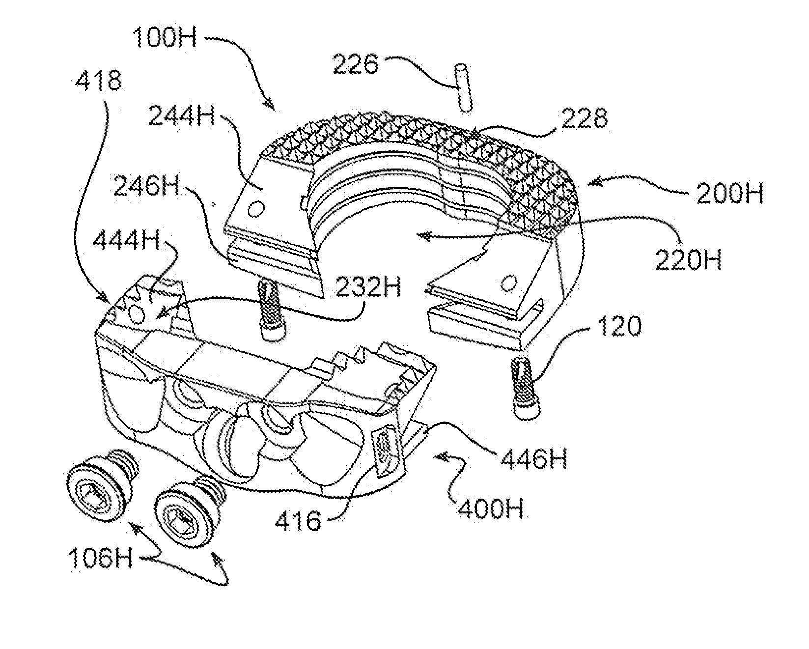
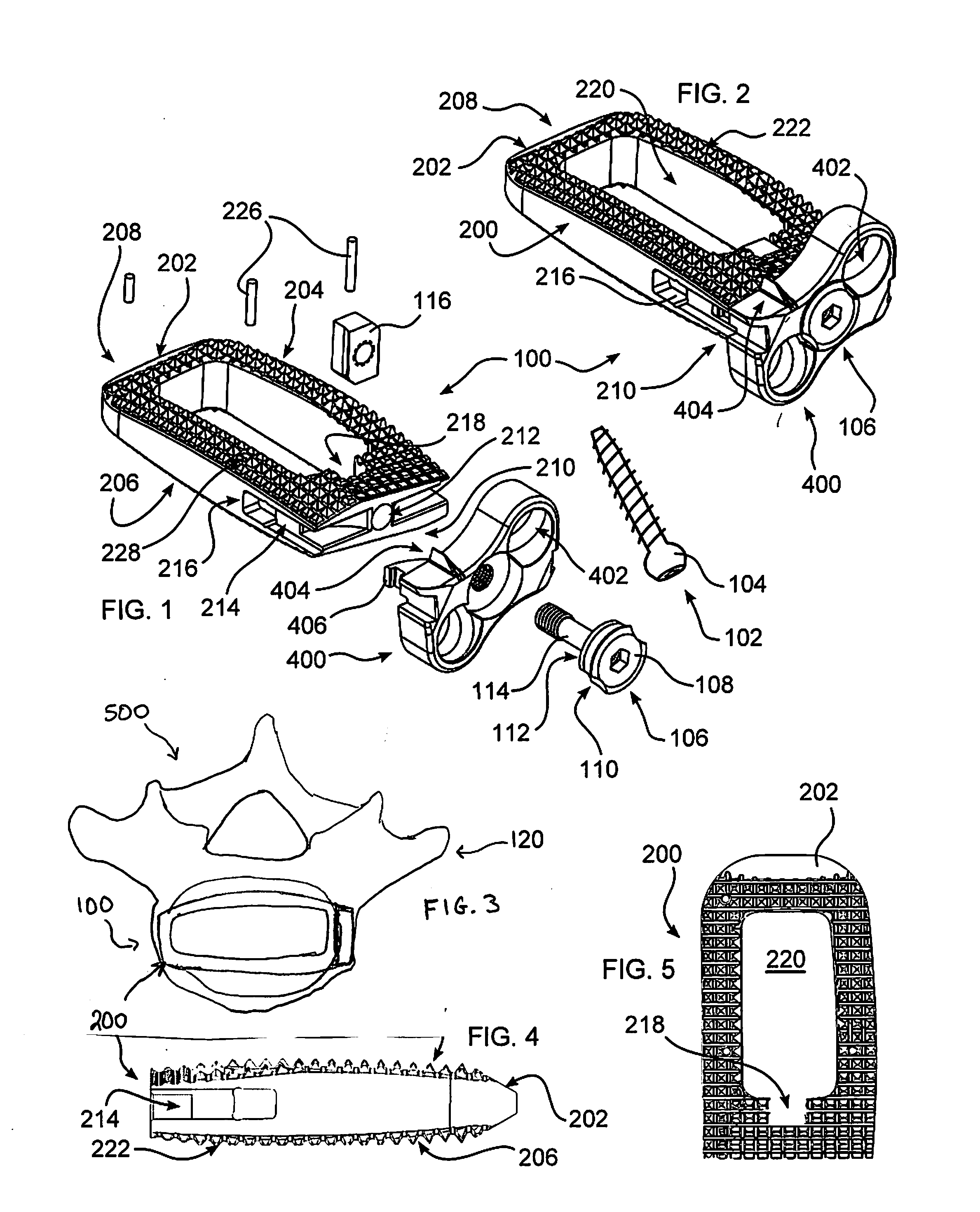
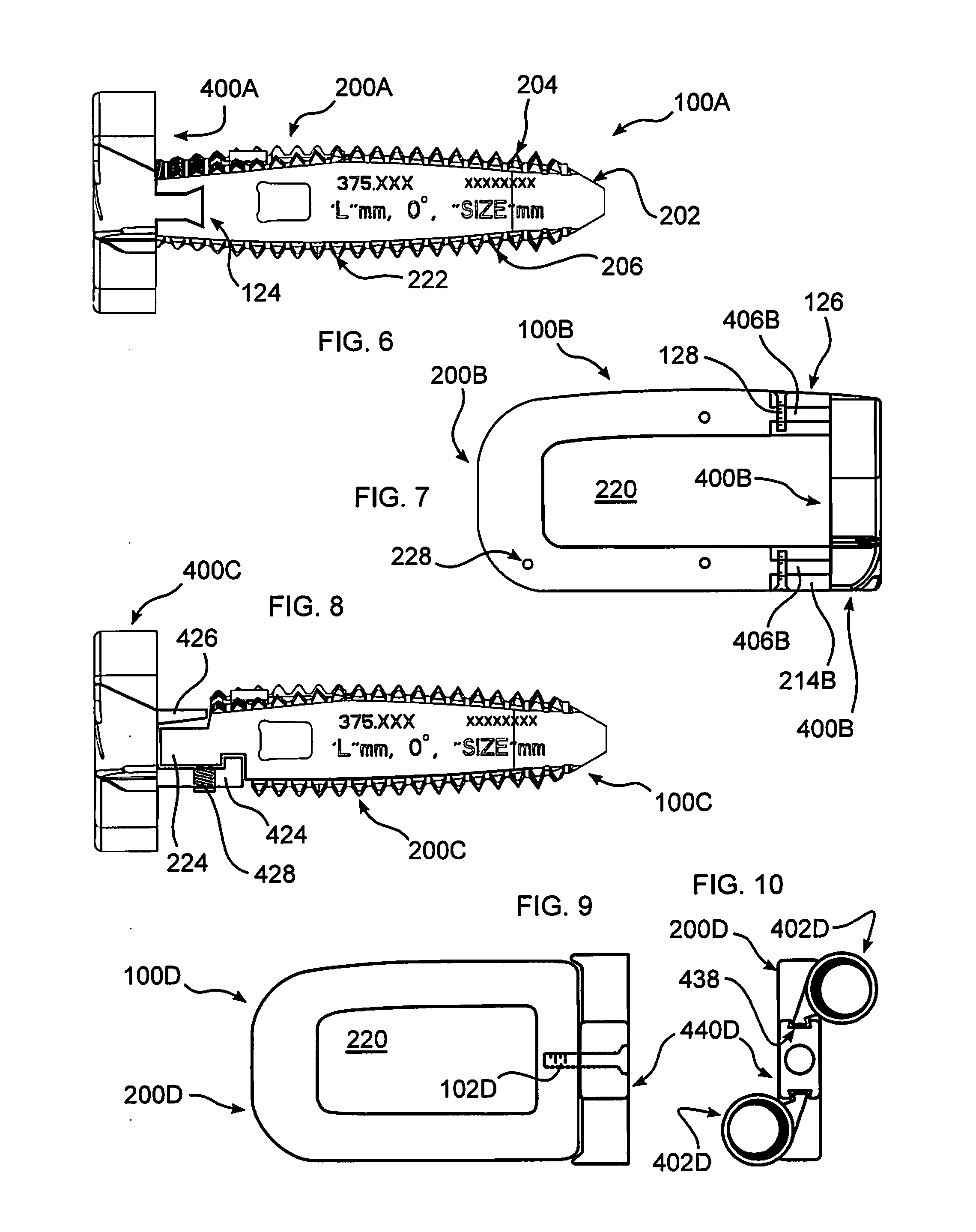
The patent describes a device for separating and stabilizing adjacent vertebrae in the spine. The device includes a plate with sockets for retaining fasteners and connecting projections for securely attaching the plate to the vertebral bodies. A spacer body is also included to fill the intervertebral space. The device can be used in a variety of ways, such as through an anterior or lateral approach, and can be inserted from a lateral approach after the removal of body tissue. The device helps to stabilize the spine and promote bone growth.

Problems solved by technology

Bones and bony structures are susceptible to a variety of weaknesses that can affect their ability to provide support and structure.
This results in a loss of water content, and ultimately a loss of height.
As a result, the nerves exiting from the spinal canal 132 become compressed and pinched, which causes pain, among other neurological deficits.

Method used


Image

  • Stabilizing Joints
  • Stabilizing Joints
  • Stabilizing Joints

Examples


Embodiment Construction

[0046]As required, detailed embodiments are disclosed herein; however, it is to be understood that the disclosed embodiments are merely examples and that the systems and methods described below can be embodied in various forms. Therefore, specific structural and functional details disclosed herein are not to be interpreted as limiting, but merely as a basis for the claims and as a representative basis for teaching one skilled in the art to variously employ the present subject matter in virtually any appropriately detailed structure and function. Further, the terms and phrases used herein are not intended to be limiting, but rather, to provide an understandable description of the concepts.

[0047]The terms “a” or “an”, as used herein, are defined as one or more than one. The term plurality, as used herein, is defined as two or more than two. The term another, as used herein, is defined as at least a second or more. The terms “including” and “having,” as used herein, are defined as comp...


PUM


Abstract

An intervertebral spacer and stabilization implant includes a plate having sockets configured for retaining a fastener passable through the socket and into an adjacent vertebral body. One or more connecting projections extend from a side of the plate, to mate with projections extending from a spacer body. A plurality of teeth project from at least one of the upper or lower surfaces of the spacer body, and a chamber is formed through the spacer body to enable bone fusion between the vertebrae. The combined plate and spacer may be inserted to lie completely within the intervertebral space, or a portion of the plate may overlie a vertebral body.

Description

FIELD OF THE INVENTION[0001]The invention relates to stabilizing joints using a spacer, and more particularly stabilizing the spine using an intervertebral spacer and plate secured by fasteners.BACKGROUND OF THE INVENTION[0002]Bones and bony structures are susceptible to a variety of weaknesses that can affect their ability to provide support and structure. Weaknesses in bony structures have numerous potential causes, including degenerative diseases, tumors, fractures, and dislocations. Intervertebral discs in the spinal column degenerate more rapidly as people grow older. This results in a loss of water content, and ultimately a loss of height. As a result, the nerves exiting from the spinal canal 132 become compressed and pinched, which causes pain, among other neurological deficits.[0003]In some cases, the spinal column requires additional support in order to address such weaknesses and compression. One technique for providing support is to insert a spacer between adjacent verteb...

Claims


Application Information

Patent Timeline
Patent Type & Authority Applications(United States)
IPC IPC(8): A61F2/44
CPCA61B17/8042A61F2/30744A61F2/447A61F2002/3008A61F2002/30331A61F2002/30387A61F2002/30433A61F2002/30448A61F2002/30492A61F2002/305A61F2002/30507A61F2002/30538A61F2002/30578A61F2002/30593A61F2002/3071A61F2002/30787A61F2002/30836A61F2220/0008A61F2310/00023A61F2/442A61F2/4455
Inventor IOTT, ANDREWSEIFERT, JODY L.PAUL, DAVID C.ADAMS, MARKGAHMAN, KEVINGLERUM, CHADDAVEPORT, DANIELALEXANDER, VICTORIA
Owner GLOBUS MEDICAL INC
Learn More