
Probe for monitoring the electrical conductivity of soil solutions

Inactive Publication Date: 2014-02-06
MOTTES ADI
View PDF3 Cites 7 Cited by
  • Summary
  • Abstract
  • Description
  • Claims
  • Application Information

AI Technical Summary

Benefits of technology

The invention allows for continuous monitoring of soil solution through a vacuum tube that maintains a parallel relationship with the sensor probe. This is made possible by using a porous ceramic material that allows ions in the ground solution to move freely into the tube. This results in accurate and reliable measurements that are not affected by sunlight.

Problems solved by technology

The drawback of this probe is the small and narrow inner space of the pottery clay which is not able to hold an EC electrode and to manage electrical conductivity tests.
The drawback of such a probe is as follows: the extremely narrow inner diameter of 2-3 mm is able to hold only an electrode with very little free space.
These devices and methods may be suitable for monitoring a large number of soil properties such as pH, phosphorus, ammonium, magnesium, chlorides, nitrates, potassium, water hardness, or other soil properties but can produce inaccurate measurements or no readings at all for Electrical Conductivity (EC) since EC is highly sensitive to continuous disturbances in the ground medium.
Every change in the volume and direction of the flow of the water as a result of irrigation or rainfall may cause the creation of a temporary physical state of lack of unity in the ground structure.
This, in turn, includes the formation of air pockets which disturb the EC measurements.
Such situation gets worse when the water content of the ground falls and as a result the electrodes lose contact with the water in the soil.
When the soil is relatively dry, the solution drawn into the porous ceramic tip may lack continuity, and thus, the EC electrodes may not carry out a measurement at all and may show a read error of the value “0”.
Thus, the prior art devices and methods are not suitable for conducting EC measurements that are reliable and accurate in all instances, as accurate EC measurements require a perfect continuity of the solution surrounding the sensor electrode.

Method used


Image

  • Probe for monitoring the electrical conductivity of soil solutions
  • Probe for monitoring the electrical conductivity of soil solutions
  • Probe for monitoring the electrical conductivity of soil solutions

Examples


Embodiment Construction

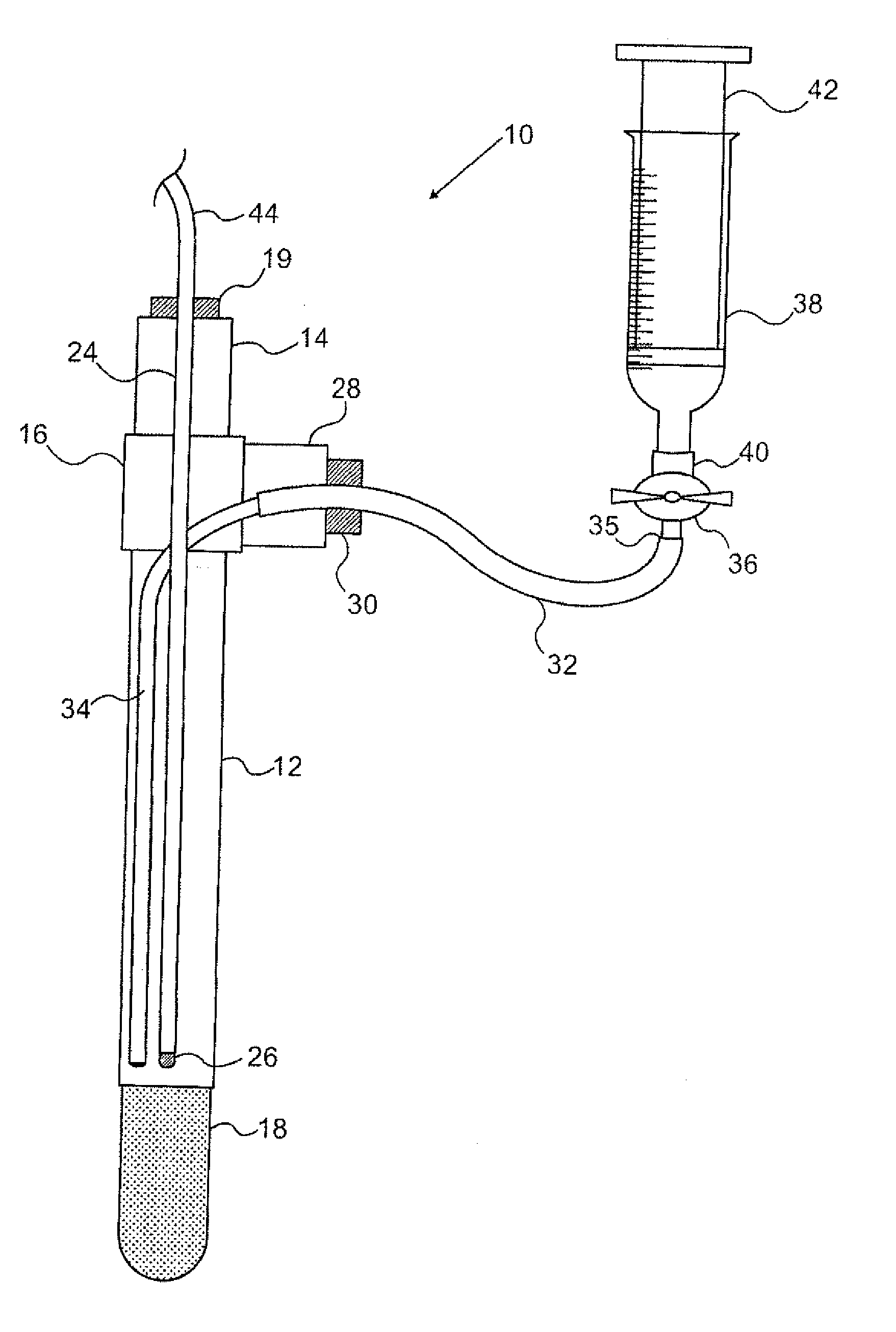
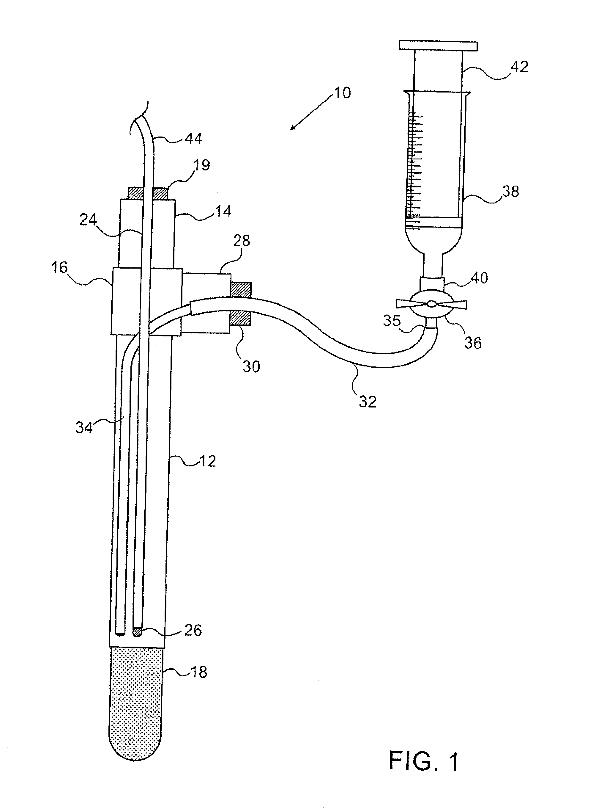
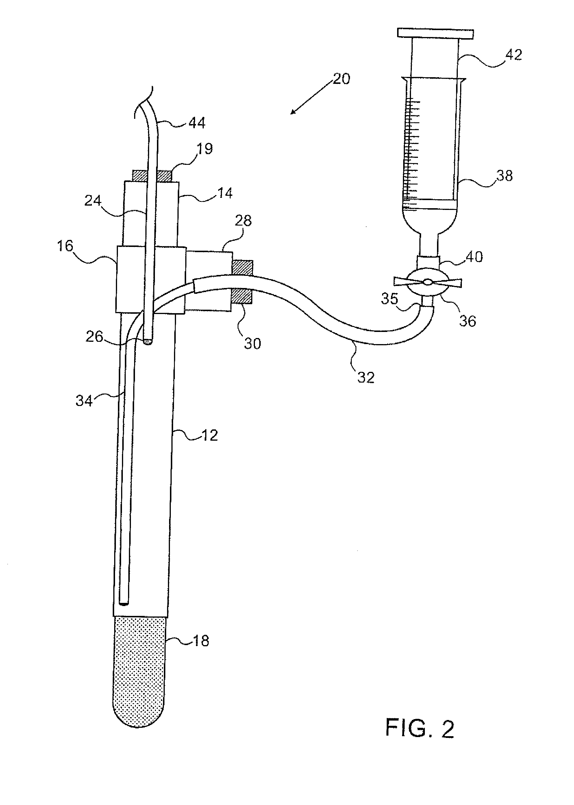
[0052]Referring to FIG. 1 there is shown a probe 10 comprised of a divided hollow tube consisting of a lower tube section 12 and an upper tube section 14. The two sections 12 and 14 are connected in series through a T fitting 16 by gluing them into the T fitting 16 hermetically. The lower tube 12 section is capped at the bottom with a porous ceramic tip 18 for inserting into soil. The upper tube section 14 is sealed at the top with a stopper 19 which has an opening through which a sensor probe 24 having a sensor electrode 26 at its tip is inserted down towards the bottom of tube section 12.

[0053]The T fitting 16 has a side aperture from which extends a hollow tube section 28 sealed (i.e., glued) therein hermetically. Tube section 28 is sealed with a stopper 30. A vacuum tube 32 is inserted through stopper 30 and is connected hermetically to a semi-rigid inner vacuum tube 34 that continues into the lower tube section 12. The other end 35 of the vacuum tube 32 is connected to a valve ...


PUM


Abstract

A probe for monitoring electrical conductivity of soil solutions is provided. The probe includes an upper hollow tube section stoppered at one end, a lower hollow tube section capped at its bottom with a porous ceramic material for inserting into soil, a T fitting connecting the other end of the upper hollow tube section in vertical alignment with the lower hollow tube section, said T fitting having an aperture which is stoppered, an electric conductivity (EC) sensor electrode inserted through the stopper of the upper hollow tube section into the lower hollow tube section, and a vacuum tube inserted through the stopper of the aperture of the T fitting extending into the lower hollow tube section. Ground solution can be withdrawn from the probe via the vacuum tube by a vacuum generator and fresh ground solution can be drawn into the probe without removing the sensor probe from the probe.

Description

[0001]This application is a continuation of international application No. PCT / IL2012 / 000213 filed on May 31, 2012 and claims the benefit of Israeli application No. 213498 filed on Jun. 12, 2011 and Israeli application No. 218431 filed on Mar. 1, 2012, which are incorporated herein by reference in their entirety and for all purposes.FIELD OF THE INVENTION[0002]The present invention relates to monitoring of chemical and physical properties of soil solutions. More specifically, the present invention relates to a probe and method for direct monitoring electrical conductivity (EC) of soil solution.BACKGROUND OF THE INVENTION[0003]The activity and productivity of all agricultural crops are strongly influenced by the level of salinity, i.e. of the total dissolved solids, in the soil solution which is easily determined by electric conductivity measurements[0004]The ability of most crops and plants to draw and extract soil water containing fertilizer by means of the roots depends on the sali...

Claims


Application Information

Patent Timeline
IPC IPC(8): G01N27/02
CPCG01N27/02G01N27/07G01N33/24
Inventor MOTTES, ADI
Owner MOTTES ADI
Learn More