
Systems and methods for controlling tower clearance in a wind turbine

a technology of tower clearance and wind turbine, which is applied in the direction of rotors, vessel construction, marine propulsion, etc., can solve the problems of blade deflection, blade deflection, and affecting the cost of energy

Inactive Publication Date: 2014-01-30
GENERAL ELECTRIC CO
View PDF9 Cites 23 Cited by
  • Summary
  • Abstract
  • Description
  • Claims
  • Application Information

AI Technical Summary

Benefits of technology

The patent describes a wind turbine control system that adjusts the pitch of its blades to control the rotation of the wind turbine rotor. This system uses a detecting unit to measure the aerodynamic thrust and speed of wind, and a compensating unit to determine the physical nodding moment of the wind turbine rotor. A driving unit then changes the pitch of the blades to adjust the physical nodding moment, which in turn controls the rotation of the wind turbine rotor. The technical effect of this system is to improve the efficiency and control of wind turbines in producing energy.

Problems solved by technology

The design of the wind turbine is instrumental in affecting the cost of energy.
However, with the increase in the turbine size, particularly blade length, blade deflection becomes a challenge.
Typically, blade deflection occurs due to the aerodynamic thrust acting on the rotor.
Some large wind turbines have been known to experience tower strikes in which a blade deflects to the point that it strikes the tower and is destroyed.
This results in a more flexible blade and may increase the possibility of tower strikes.
However, these strategies will give the clearance information only when the blades are in front of the tower, and thus likely to be less effective for dynamically changing tower clearance.

Method used


Image

  • Systems and methods for controlling tower clearance in a wind turbine
  • Systems and methods for controlling tower clearance in a wind turbine
  • Systems and methods for controlling tower clearance in a wind turbine

Examples


Embodiment Construction

[0015]As will be described in detail hereinafter, various embodiments of an exemplary wind turbine control system for adjusting the tower clearance in an operating wind turbine and methods for adjusting the tower clearance in the operating wind turbine are presented. By employing the methods and the various embodiments of the wind turbine control systems described hereinafter, tower clearance may be easily adjusted irrespective of the size of blades in the wind turbine. Also, the wind turbine control system may help in increasing the size of the wind turbine, which in turn reduces the cost of energy.

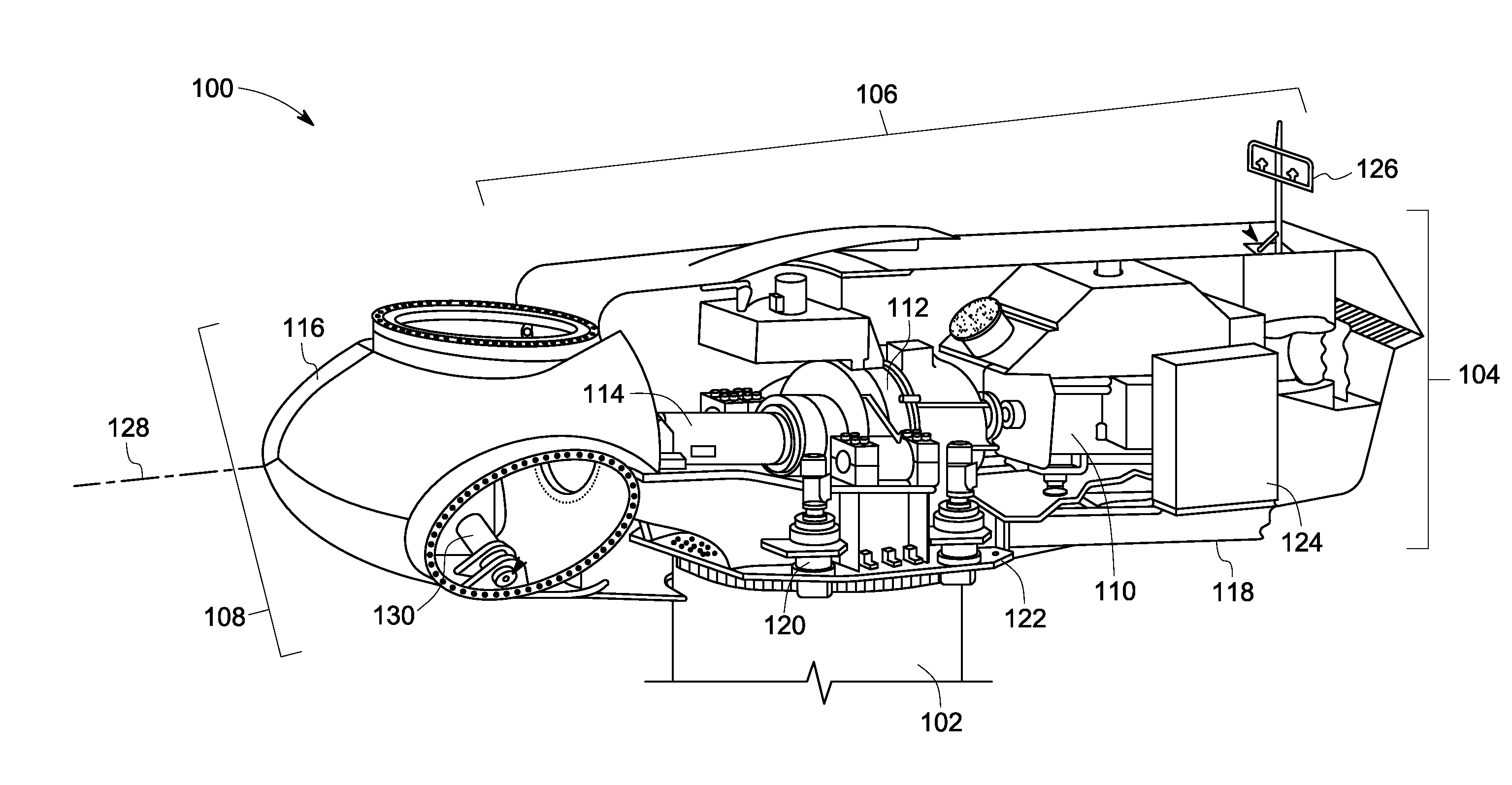
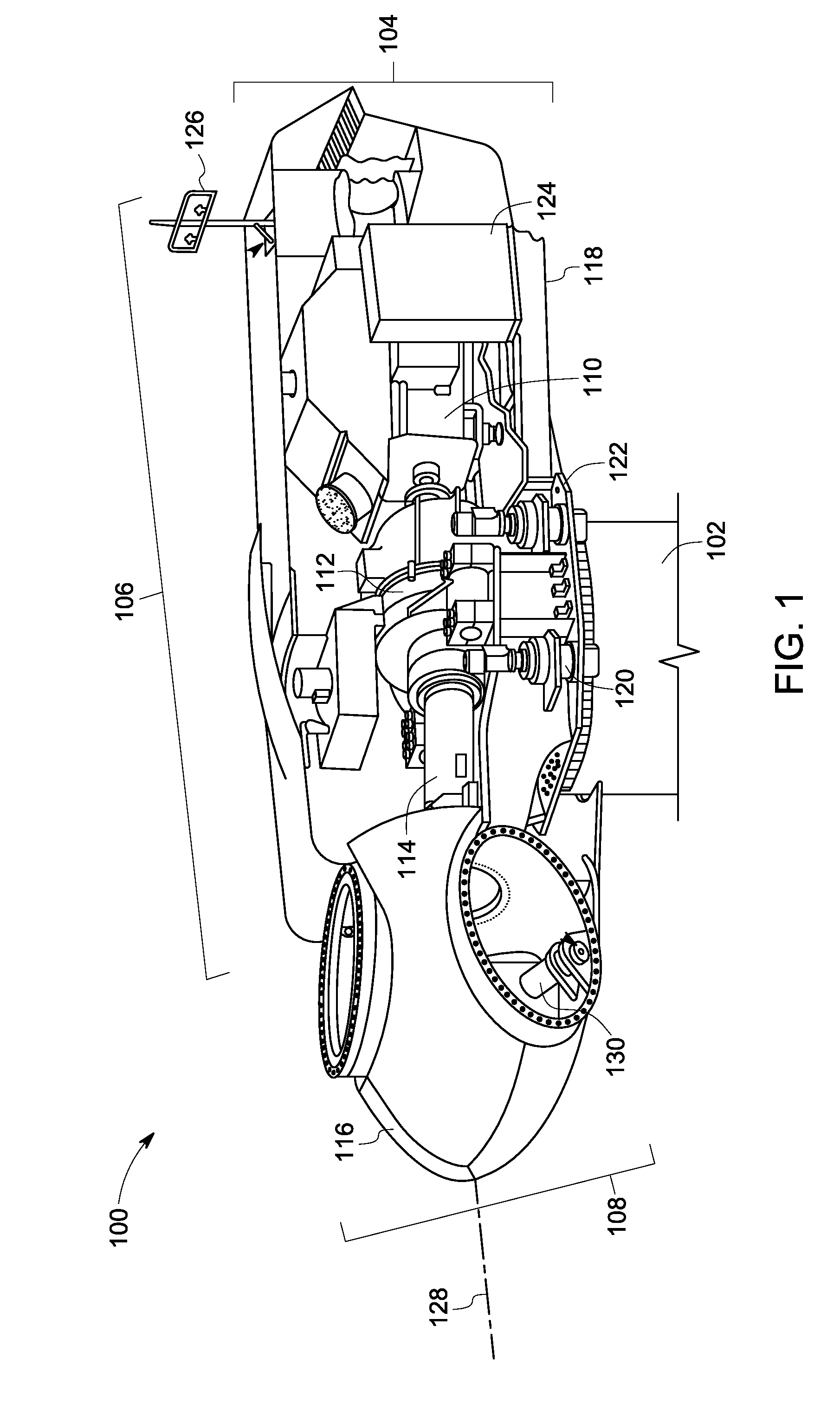
[0016]Turning now to the drawings, and referring to FIG. 1, a perspective view of a wind turbine 100, in accordance with aspects of the present disclosure, is depicted. The wind turbine 100 is configured to convert kinetic energy of wind passing across the wind turbine 100 into electrical energy. Particularly, the wind turbine 100 includes a plurality of mechanical moving parts that aid ...


PUM


Abstract

A wind turbine control system includes a detecting unit for adjusting a reference nodding moment of a wind turbine rotor based on at least one of an aerodynamic thrust on the wind turbine rotor and a speed of wind; a compensating unit for determining a physical nodding moment of the wind turbine rotor, comparing the physical nodding moment with the reference nodding moment, and using the comparison to compute a pitch angle command for at least one wind turbine blade; and a driving unit for changing a pitch of the at least one blade based on the pitch angle command to control the physical nodding moment of the wind turbine rotor.

Description

BACKGROUND[0001]The disclosure relates generally to a wind turbine and more specifically to systems and methods for adjusting the tower clearance in an operating wind turbine.[0002]A wind turbine is designed to produce electrical energy at a wide spectrum of wind speeds. When wind of sufficient speed passes across the blades, the rotor is rotated to generate electrical energy in the generator. The design of the wind turbine is instrumental in affecting the cost of energy.[0003]In a conventional wind turbine, the cost of energy is significantly reduced by increasing the size of the wind turbine. However, with the increase in the turbine size, particularly blade length, blade deflection becomes a challenge. Typically, blade deflection occurs due to the aerodynamic thrust acting on the rotor.[0004]Some large wind turbines have been known to experience tower strikes in which a blade deflects to the point that it strikes the tower and is destroyed. Furthermore, many wind turbine manufact...

Claims


Application Information

Patent Timeline
IPC IPC(8): F03D7/02
CPCF03D7/0224F03D7/00F05B2240/912F05B2270/17Y02E10/728F03D17/00Y02E10/72
Inventor KAMMER, LEONARDO CESARARORA, DHIRAJ
Owner GENERAL ELECTRIC CO
Learn More