
Steam supply circuit from a turbine

Active Publication Date: 2014-01-30
GENERAL ELECTRIC TECH GMBH
View PDF14 Cites 1 Cited by
  • Summary
  • Abstract
  • Description
  • Claims
  • Application Information

AI Technical Summary

Benefits of technology

The invention aims to avoid using a manifold, which helps reduce pressure drops and the associated elbows. This results in improved installation performance. In simple terms, it means that the invention makes the system more efficient and effective.

Problems solved by technology

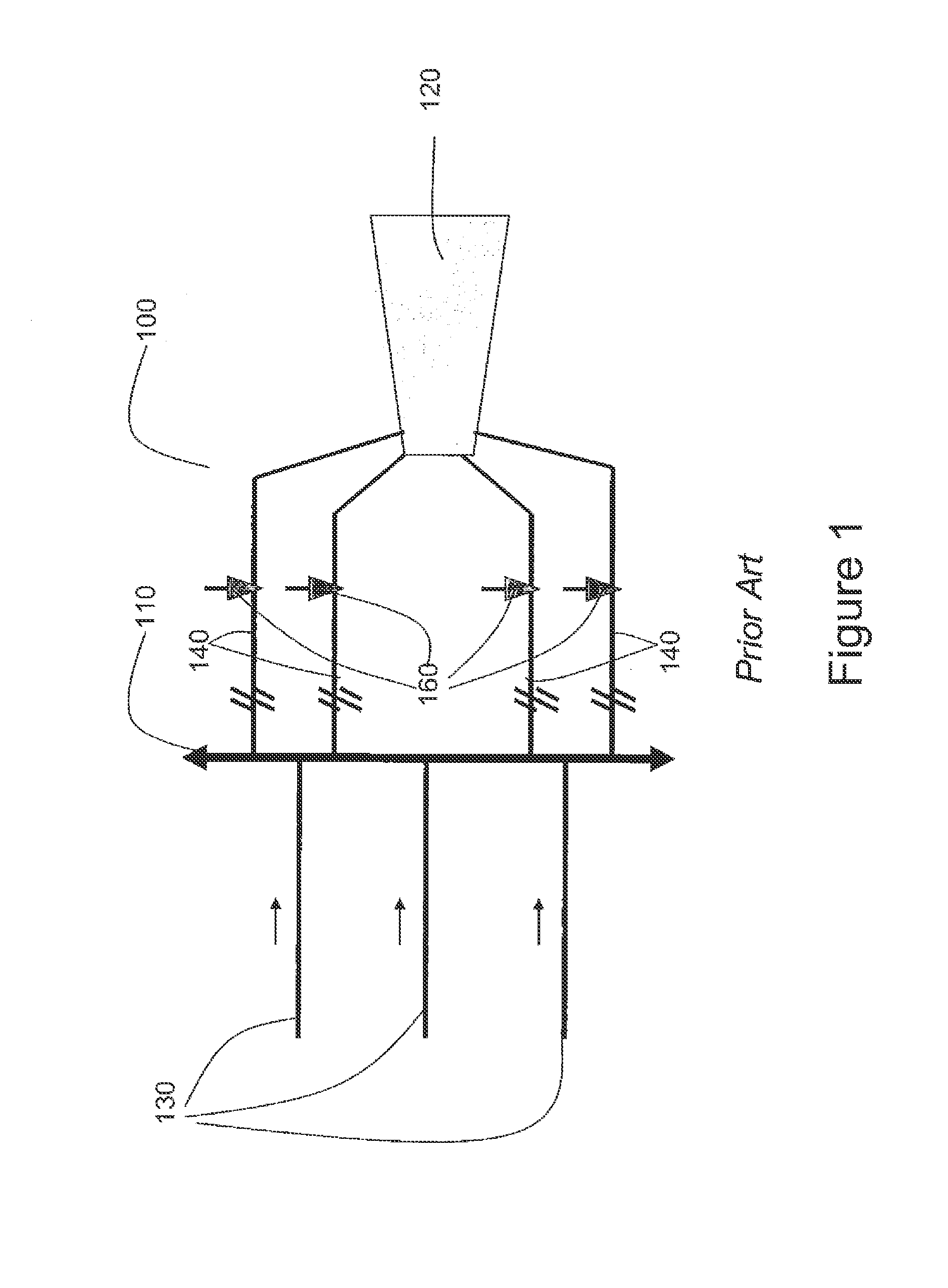
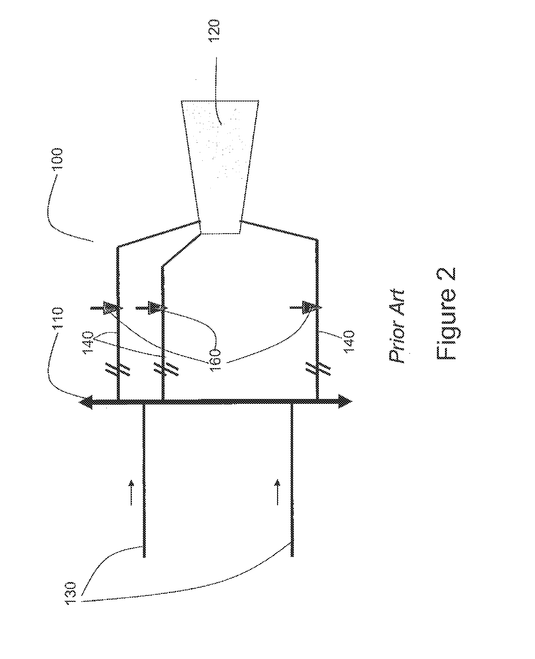
Such devices in particular have the drawback of suffering significant pressure drops.
Indeed, in this type of device, the fluid flowing through the lines and passing through a manifold is subject to greater friction on account of a longer feed circuit including numerous direction changes and irregularities.
Pressure drops adversely affect the performance of the installation and ultimately reduce the electrical power available.

Method used


Image

  • Steam supply circuit from a turbine
  • Steam supply circuit from a turbine
  • Steam supply circuit from a turbine

Examples


Embodiment Construction

[0006]The invention is intended to resolve the drawbacks in the prior art, in particular the problem of ducting steam to feed a turbine driving a generator. It is in particular intended to propose an optimized steam feed circuit between a functional steam generator set on the one hand and a turbine driving a generator on the other, enabling the performance of such a turbine to be increased. The heat source of the functional steam-generator set may be equally nuclear or fossil fuel.

[0007]To do so, and according to a first feature, a steam feed circuit of a turbine is proposed, incorporating n main steam lines and n′ steam admission lines to the turbine, the number n′ of steam admission lines to the turbine being strictly greater than the number n of main steam lines, characterized in that it includes n direct steam admission lines to the turbine linking the n links of the main steam lines directly to the steam admission lines to the turbine. The number n of main steam lines and the n...


PUM


Abstract

The technical field of the invention is steam turbines including a steam feed circuit based on a functional steam generator set that may be nuclear- or fossil-fuel powered, and in particular a steam feed circuit (1) of a turbine (2), comprising n main steam lines (3) and n′ steam admission lines (4) to the turbine, the number n′ of steam admission lines (4) to the turbine being strictly greater than the number n of main steam lines (3), characterized in that there are n direct steam admission lines (5) to the turbine linking the as main steam lines (3) directly to the steam admission lines (4) to the turbine.

Description

TECHNICAL FIELD OF THE INVENTION[0001]The technical field of the invention is turbines driving a generator and including a steam feed circuit. The heat source of a steam generator may be equally nuclear or fossil fuel.PRIOR ART[0002]The problem of supplying steam to a turbine driving a generator from a functional steam generator set arranged in parallel, each delivering the steam at substantially the same pressure, is already addressed by several devices, in particular placing a manifold between the different main steam lines and the turbine steam admission lines. This manifold enables all of the steam supplied by the functional steam generator set to be collected and to be distributed to the first wheel of the steam turbine via a set of steam admission lines, each having adjustment means.[0003]Indeed, an electricity generation installation includes a turbine supplied with steam by one or more steam generators. The main steam lines are defined below as lines running from the steam g...

Claims


Application Information

Patent Timeline
IPC IPC(8): F01D1/18
CPCF01D1/18F01D1/023F01D15/10F01D17/18F02C1/05
Inventor JOURDAIN, VINCENTVIOLA, BERNARDMILET, DAMIEN
Owner GENERAL ELECTRIC TECH GMBH
Learn More