Container

a container and container technology, applied in the field of containers, can solve the problems of not being able to carry other than cylindrical cargo items, and the container is not useful for the continued transportation, and achieve the effects of avoiding damage to the cargo, reducing the mass centre, and improving the friction against cylindrical objects

Active Publication Date: 2014-01-30
OY LANGH SHIP AB
View PDF4 Cites 3 Cited by
  • Summary
  • Abstract
  • Description
  • Claims
  • Application Information

AI Technical Summary

Benefits of technology

The invention is a new container that can be easily modified to carry a variety of cargo items, including cylindrical items. The container is designed with a wedge-shaped support member that allows for a uniform chute and a small transition area when in use. The support member can be modified at both ends with pivot mechanisms for added strength and flexibility. The container also has a multitude of support members that can be easily turned manually, making it easy to modify the structure for different types of cargo. The container is designed to minimize damage to the cargo during transport and can be used with various types of loads. The pivot mechanism is designed to prevent objects from sliding and can also be modified to improve friction against cylindrical objects without causing excessive loads to the pivot mechanism.

Problems solved by technology

A problem with this prior art container is that it is not suitable for carrying other than cylindrical cargo items.
When used for carrying a cylindrical item from point A to point B, the cylindrical item being unloaded in point B, the container is not useful for the continued transport unless other cylindrical objects are to be carried from point B. As a result, the container returning from point B is typically empty until reloaded again in point A (or some other point) with cylindrical cargo items.

Method used


Image

  • Container
  • Container
  • Container

Examples


Embodiment Construction

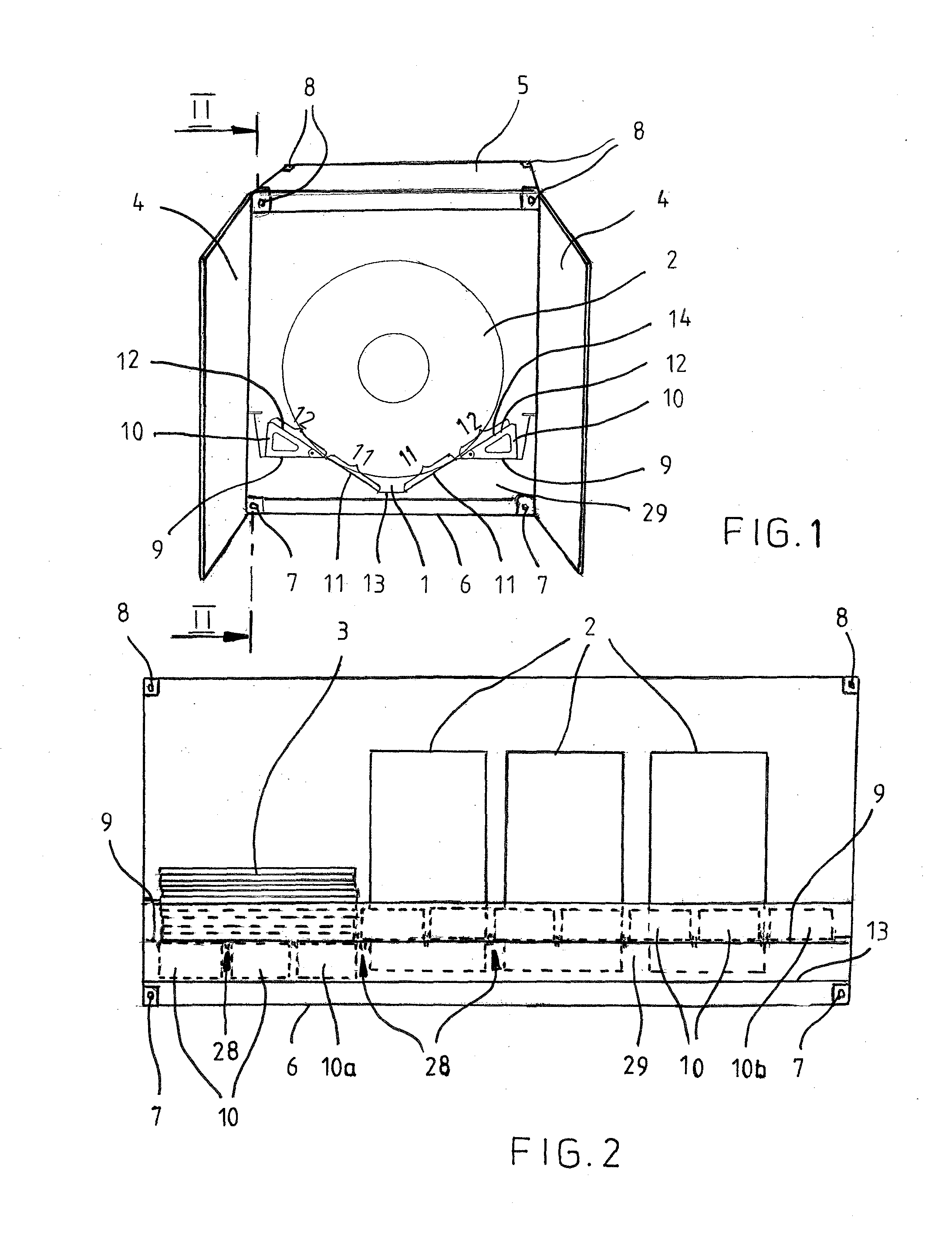
[0019]FIG. 1 is a perspective end view illustrating a container of the invention and FIG. 2 is a side view illustrating the container of FIG. 1 along a section line II-II of FIG. 1. The dimensions of the container correspond to those of a standard container of 20 feet. Hence the width of the container is 8 feet and the height of the container is approximately 8.5 feet.

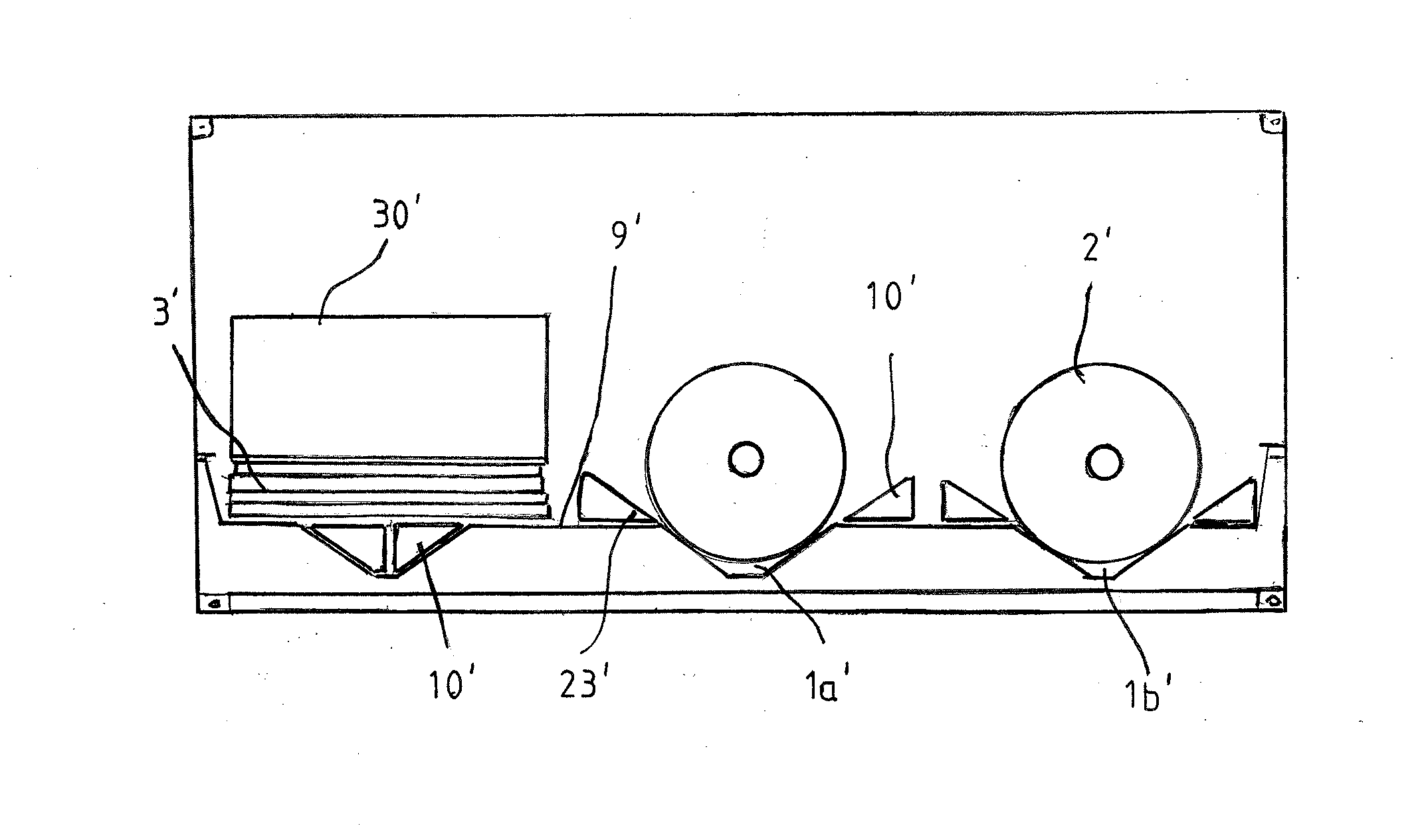
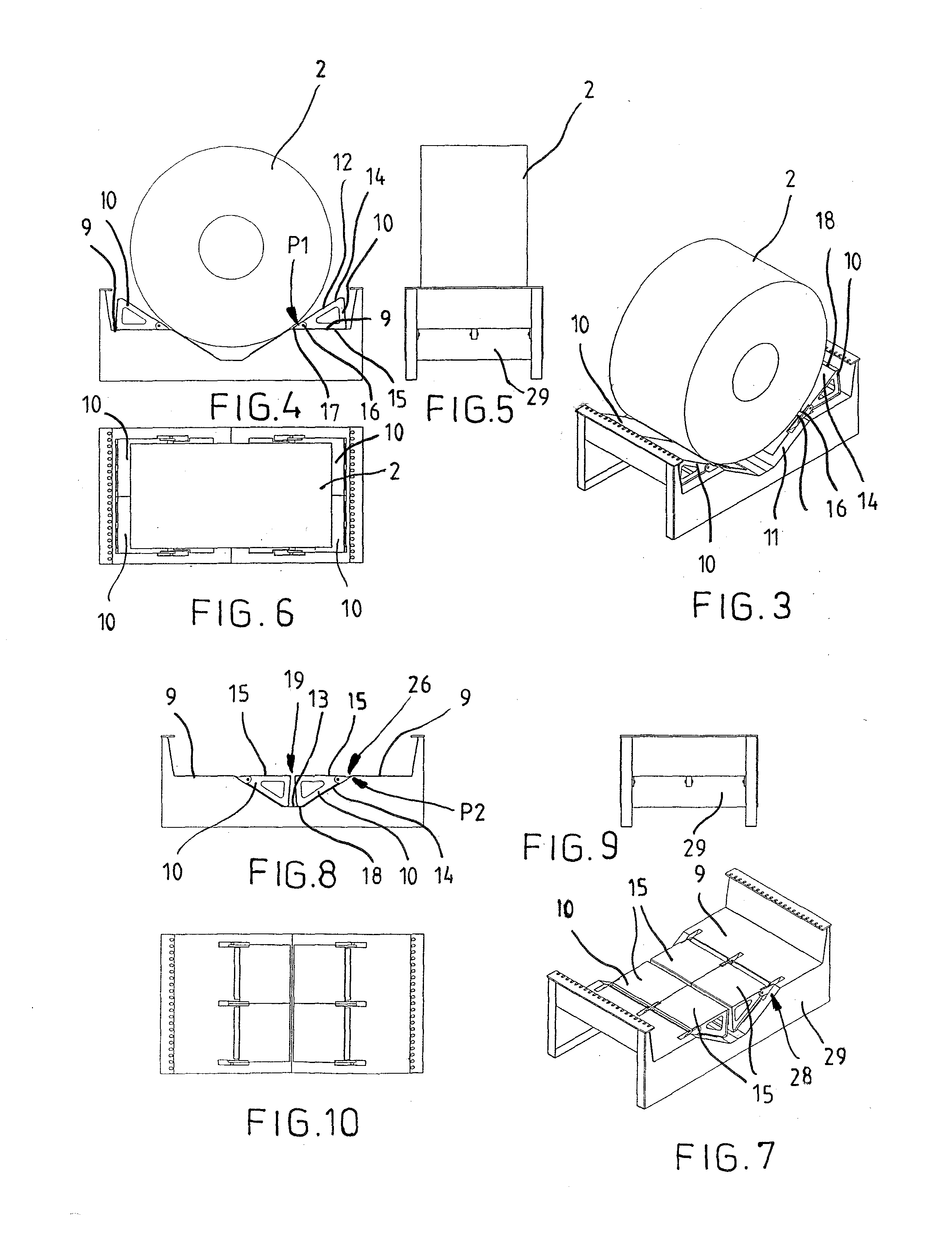
[0020]The container comprises a chute 1 in a longitudinal direction thereof, with three reels 2 loaded in the chute. The reels are steel reels, but they could be paper reels or other cylindrical objects, such as tubes. At one end of the container there is a plate load 3 (see FIG. 2). An operating mechanism included in the container allows a desired length to be chosen for the chute 1. In FIG. 2 the length of the chute 1 has been set equal to about three reels, the chute being filled close to one end thereof with wedge-like support members 10 belonging to the operating mechanism. The structure and operation of the suppo...


PUM


Abstract

A container includes a chute for supporting reels, the chute including a bottom, a lower wall zone, an upper wall zone, and a support frame for supporting the chute. The container has a horizontal support plane on both sides of the chute, the upper wall zone being formed by a first support surface of a wedge-like support member placed onto the support plane, a second support surface of the support member resting against the support plane when the support member is in a first use position; a pivot mechanism allowing the support member to be turned in relation to the support frame so that the first support surface sets against the lower wall zone of the chute and the second support surface sets onto the same height level as the support plane for forming a uniform loading plane and for placing the support member to a second use position.

Description

BACKGROUND OF THE INVENTION[0001]The invention relates to a container comprising a chute for supporting cylindrical objects, such as reels and tubes, the chute comprising a bottom and a wall structure that extends upward and outward from the bottom of the chute on both sides thereof and is bipartite on both sides of the chute, comprising a lower wall zone and an upper wall zone as an extension of the lower wall zone, and a support frame for supporting the chute.[0002]This type of container is known from publication WO 2009 / 118459 A1. A problem with this prior art container is that it is not suitable for carrying other than cylindrical cargo items. When used for carrying a cylindrical item from point A to point B, the cylindrical item being unloaded in point B, the container is not useful for the continued transport unless other cylindrical objects are to be carried from point B. As a result, the container returning from point B is typically empty until reloaded again in point A (or ...

Claims


Application Information

Patent Timeline
Patent Type & Authority Applications(United States)
IPC IPC(8): B65D25/10B65D85/02
CPCB65D85/02B65D25/103B65D90/006B65D2590/0058B65D19/44B65D85/04B65D88/12B65D90/00
Inventor LANGH-LAGERLOF, LAURA
Owner OY LANGH SHIP AB
Why Eureka
Try Eureka