Fluid Backup Preventing System and Method of Use Thereof

Active Publication Date: 2014-01-30
7525443 CANADA
View PDF15 Cites 7 Cited by
  • Summary
  • Abstract
  • Description
  • Claims
  • Application Information

AI Technical Summary

Benefits of technology

The patent is about a system that prevents fluid from flowing backwards in a conduit. It includes a sensor to detect fluid levels, a sealing mechanism to prevent fluid from leaking into the conduit, and a main power source to activate the sealing mechanism. The system also has a control mechanism that is not affected by the speed of the fluid flow. Additionally, the system has a splash guard to prevent false signals caused by fluid splashes during normal use. The system includes an inflatable bladder that can be inflated to seal the conduit and block fluid flow. Overall, the system ensures safe and reliable prevention of fluid backup in the conduit.

Problems solved by technology

In a building or other structures serviced via an underground sewer line, it sometimes occurs that the main sewer line or the branch line leading from the building to the main sewer line becomes clogged.
Indeed, the problem of basement flooding from sewer line water backup flow has become prevalent in recent years.
The backup may be caused by a variety of problems including when the flow capacity of the sewer system is exceeded by the rain water inflow rate into the system.
The risk of water backup is present in most storm sewer systems where the storm sewers are rarely of a sufficient size to accommodate unusually heavy rain storms.
This risk is sometimes present in sanitary sewer system where there is a water leakage into the sewer system through manholes, cracks in sewer line joints or where improper roof down spout connections are made to the system which normally should carry only the water and sewage draining from sinks, toilets, washing machines drain lines and basement floor drains.
Clogging of the sewer line may be caused by many factors including broken or misaligned pipes.
Such broken or misaligned pipes present projections, ridges or sharp bends on which bulk material hangs up and causes a nucleus fore clogging.
Whatever the cause of the clog, the effect is that the sewage becomes backed up in the line and eventually the backflow will overflow from the fixtures and drains in the building.
While this type of clean out allows for access to the sewer line for removal of clog, it does not prevent the backflow or sewage through the sewer line which will eventually overflow from the fixtures or drain inside of the building.
However, many home owners simply do not wish to incur such systems.
However, these pivotal gates are only efficient when the fluid flow inside the sewer is at fast speed, since the gate will then be forcibly pivotally biased against its annular seat inside the sewer duct by the hydrodynamic forces.
Such pivotal gate valve systems are however ineffective in conditions of sewer duct clogging, since the fluid level inside the sewer duct raises quite progressively, and the fluid flow speed is usually small, which would not provide a hydrodynamic force suitable for pivotally biasing the pivotal gate against its annular seat in a fluid tight fashion.
Inflatable bladders may be used in place of pivotal gate valves, although these bladders create a phenomenon of fluid flow turbulence.
Moreover, such inflatable bladders may require manual handling to be deflated.
Furthermore, most conventional fluid backflow mitigating prior art systems are not efficient in early detection of fluid and thus are relatively unreliable and inefficient.

Method used


Image

  • Fluid Backup Preventing System and Method of Use Thereof
  • Fluid Backup Preventing System and Method of Use Thereof
  • Fluid Backup Preventing System and Method of Use Thereof

Examples


Embodiment Construction

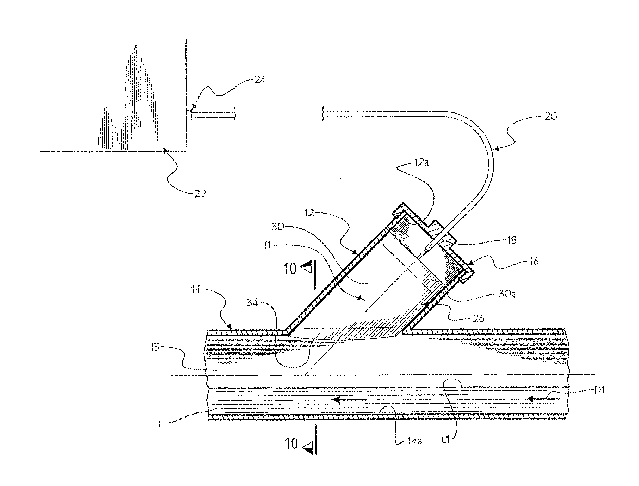
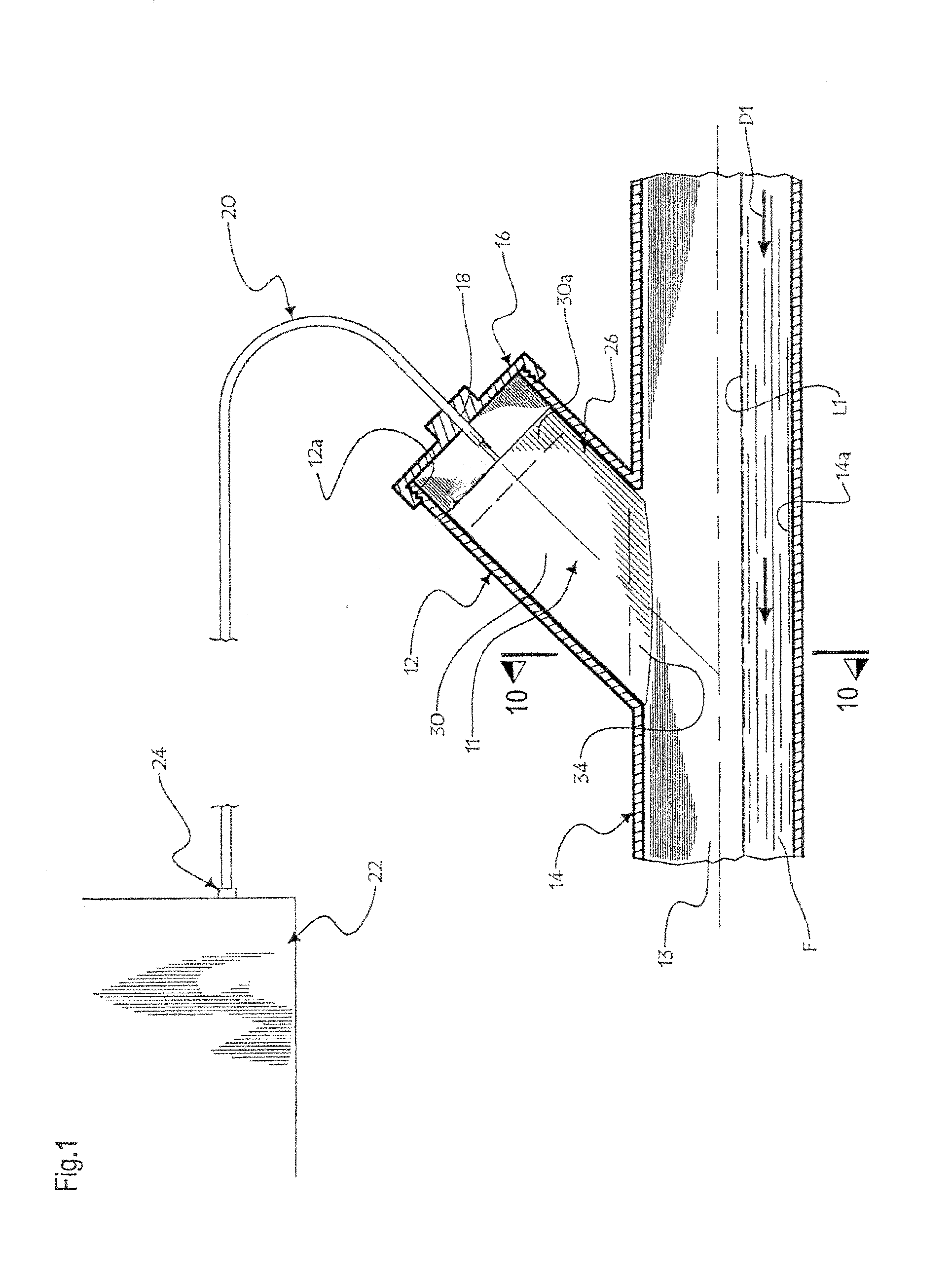
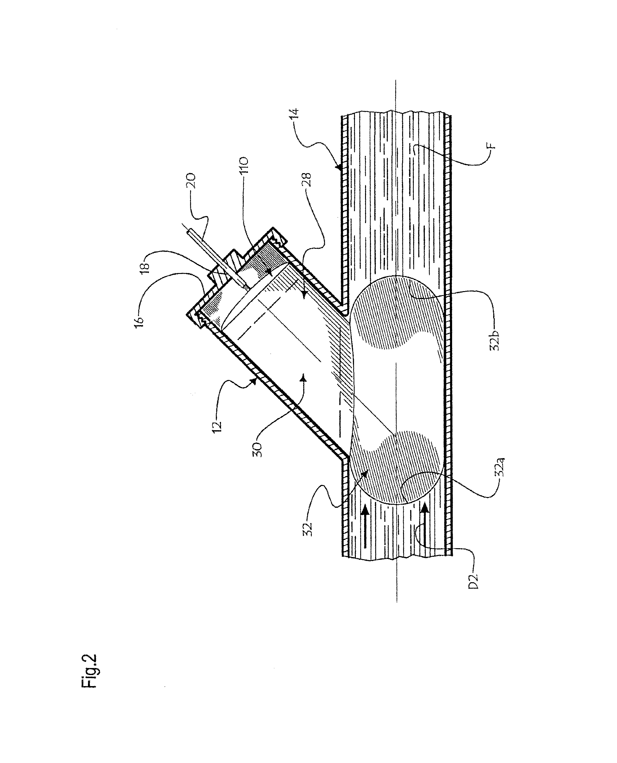
[0051]Referring to FIGS. 1 and 2, there is shown a fluid backup preventing system 11 in accordance with an embodiment of the present disclosure mounted into a clean-out duct 12 transversely opening into the channel 13 of sewer conduit 14. A fluid F, for example a liquid, may flow inside channel 13 at a low fluid level L1, along a normal flow direction D1. Although the present disclosure refers to the positioning of parts of the system 11 in the clean-out duct 12, it is pointed out that any other arrangement may be used for the positioning of fluid blocking components in the channel 13 of any type of conduit 14 (e.g., gas pipeline).

[0052]The clean-out duct 12 is preferably provided with a distal threaded segment 12 a so as to threadingly receive a mounting cap 16 provided with a cap aperture 18 extending centrally there through. The cap aperture 18 is configured and sized so as to fittingly receive at an intermediate section a cable sleeve 20 for protectively enclosing various operat...


PUM


Abstract

An apparatus for continuously controlling fluid flow in a sewer conduit, comprising: a) moisture sensors detecting levels of fluid in this conduit; b) an inflatable bladder, mounted in the sewer conduit for releasably sealing in fluid tight fashion a section of this conduit; an air compressor, for inflating the bladder; and a control box including a CPU, sensitive to the moisture sensor and actuating the air compressor responsively to conduit fluid level conditions reaching beyond a preset threshold value. The performance of the apparatus is independent of the speed of fluid flow in the sewer conduit.

Description

CROSS-REFERENCE TO RELATED APPLICATIONS[0001]This patent application is a continuation in part of U.S. patent application Ser. No. 12 / 885,680 filed on Sep. 20, 2010 which is integrated herein by reference. The application Ser. No. 12 / 885,680 was also a continuation in part of U.S. patent application Ser. No. 11 / 955,990, filed on Dec. 13, 2007 now abandoned.FIELD OF THE INVENTION[0002]The present disclosure relates to the field of fluid flow control systems concerned with fluid backup or fluid leaks, for sewer ducts, gas pipelines, and the like.BACKGROUND OF THE INVENTION[0003]There exists a plurality of situations wherein it is desirable to control accidental fluid backup flow in specific circumstances, or to monitor the fluid flow in pipes.[0004]In a building or other structures serviced via an underground sewer line, it sometimes occurs that the main sewer line or the branch line leading from the building to the main sewer line becomes clogged. Indeed, the problem of basement floo...

Claims


Application Information

Patent Timeline
IPC IPC(8): E03F7/04
CPCE03F7/04F16K7/10Y10T137/2521Y10T137/7306Y10T137/7761Y10T137/7769Y10T137/8342
Inventor SAVARIA, PATRICK
Owner 7525443 CANADA
Why Eureka
Try Eureka