Fluid backup preventing system, and method of use thereof

a backup prevention and fluid technology, applied in the direction of diaphragm valves, valve details, operating means/releasing devices, etc., can solve the problems of basement flooding from sewer line water backup flow, water backup risk, and clogging of main sewer line or branch line leading from the building to the main sewer line, so as to prevent fluid flow turbulence and rapidly and accurately detect the fluctuation of fluid

Inactive Publication Date: 2009-06-18
GESTION AQUA BCS
View PDF25 Cites 8 Cited by
  • Summary
  • Abstract
  • Description
  • Claims
  • Application Information

AI Technical Summary

Benefits of technology

[0026]Preferably, said clean-out duct defines an annular recess fully clearing said channel, said conduit sealing means including an inflatable bladder mounted into said annular recess, and inflating means for inflating the bladder, said bladder when in an inoperative condition remaining fully inside said annular recess and fully clearing said channel to prevent fluid flow turbulence in the conduit when deflated, and when in an operative inflated condition further extending radially into said channel and fully sealingly closing said channel.
[0027]The present invention therefore provides a system for blocking fluid flow within a conduit and utilizing an inflatable component which is located permanently in the conduit or a section that allows access to the conduit wanted to protect from fluid flow backup. An electrical moisture sensor capable of rapidly and accurately detecting the fluctuation of fluid in a conduct and transmitting the information to the circuitry forms part of the invention.

Problems solved by technology

In a building or other structures serviced via an underground sewer line, it sometimes occurs that the main sewer line or the branch line leading from the building to the main sewer line becomes clogged.
Indeed, the problem of basement flooding from sewer line water backup flow has become prevalent in recent years.
The backup may be caused by a variety of problems including when the flow capacity of the sewer system is exceeded by the rain water inflow rate into the system.
The risk of water backup is present in most storm sewer systems where the storm sewers are rarely of a sufficient size to accommodate unusually heavy rain storms.
This risk is sometimes present in sanitary sewer system where there is a water leakage into the sewer system through manholes, cracks in sewer line joints or where improper roof down spout connections are made to the system which normally should carry only the water and sewage draining from sinks, toilets, washing machines drain lines and basement floor drains.
Clogging of the sewer line may be caused by many factors including broken or misaligned pipes.
Such broken or misaligned pipes present projections, ridges or sharp bends on which bulk material hangs up and causes a nucleus fore clogging.
Whatever the cause of the clog, the effect is that the sewage becomes backed up in the line and eventually the backflow will overflow from the fixtures and drains in the building.
While this type of clean out allows for access to the sewer line for removal of clog, it does not prevent the backflow or sewage through the sewer line which will eventually overflow from the fixtures or drain inside of the building.
However, many home owners simply do not wish to incur such systems.
However, these pivotal gates are only efficient when the fluid flow inside the sewer is at fast speed, since the gate will then be forcibly pivotally biased against its annular seat inside the sewer duct by the hydrodynamic forces.
Such pivotal gate valve systems are however ineffective in conditions of sewer duct clogging, since the fluid level inside the sewer duct raises quite progressively, and the fluid flow speed is usually small, which would not provide a hydrodynamic force suitable for pivotally biasing the pivotal gate against its annular seat in a fluid tight fashion.
Inflatable bladders may be used in place of pivotal gate valves, although these bladders create a phenomenon of fluid flow turbulence.
Furthermore, most conventional fluid backflow mitigating prior art systems are not efficient in early detection of fluid and thus are relatively unreliable and inefficient.

Method used


Image

  • Fluid backup preventing system, and method of use thereof
  • Fluid backup preventing system, and method of use thereof
  • Fluid backup preventing system, and method of use thereof

Examples


Embodiment Construction

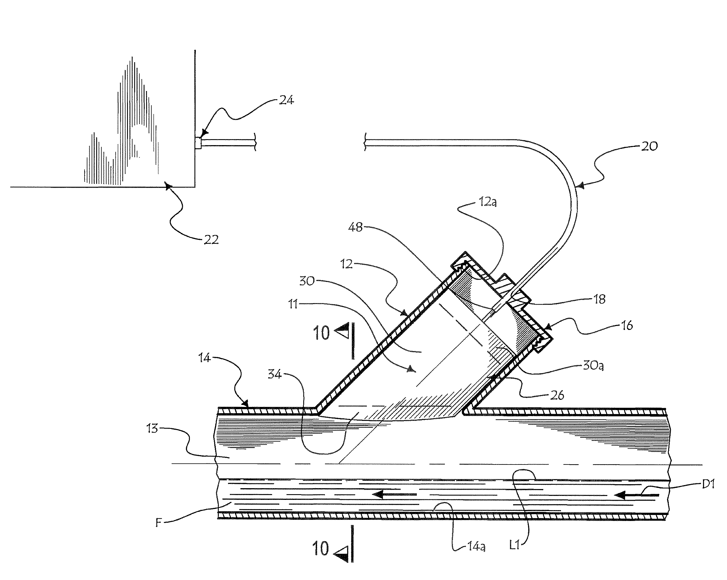
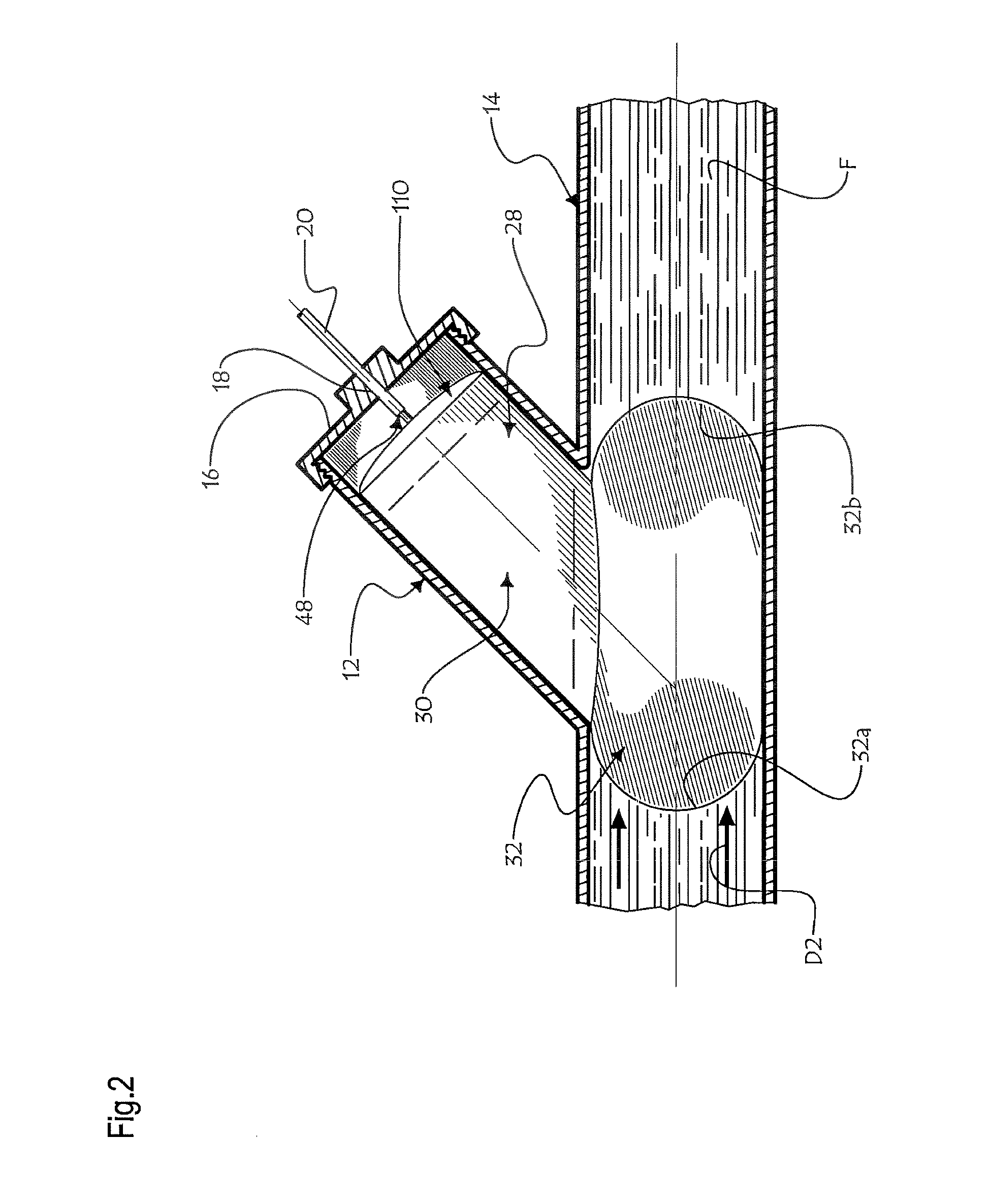
[0042]Referring to FIGS. 1 and 2, there is shown a fluid backup preventing system 11 in accordance with an embodiment of the present invention mounted into a clean-out duct 12 transversely opening into the channel 13 of sewer conduit 14. A fluid F, for example a liquid, may flow inside channel 3 at a low fluid level L1, along a normal flow direction D1.

[0043]The clean-out duct 12 is preferably provided with a distal threaded segment 12a so as to threadingly receive a mounting cap 16 provided with a cap aperture 18 extending centrally there through. The cap aperture 18 is configured and sized so as to fittingly receive at an intermediate section of a cable sleeve 20 for protectively enclosing various operative cables (pneumatic line 36 and electrical wires 43, 43′, 43″, 43′″) hereinafter disclosed and also for supporting the valve components in a suitable overlying relationship relative to the sewer conduit 14.

[0044]As mentioned previously, it should be understood that although the f...


PUM


Abstract

An apparatus for continuously controlling fluid flow in a sewer conduit, comprising: a) moisture sensors detecting levels of fluid in this conduit; b) an inflatable bladder, mounted in the sewer conduit for releasably sealing in fluid tight fashion a section of this conduit; an air compressor, for inflating the bladder; and a control box including a CPU, sensitive to the moisture sensor and actuating the air compressor responsively to conduit fluid level conditions reaching beyond a preset threshold value. The performance of the apparatus is independent of the speed of fluid flow in the sewer conduit.

Description

FIELD OF THE INVENTION[0001]The present invention relates to the field of fluid flow control systems concerned with a fluid backup preventing system for sewer ducts and the like.BACKGROUND OF THE INVENTION[0002]There exists a plurality of situations wherein it is desirable to control accidental fluid backup flow in specific circumstances.[0003]In a building or other structures serviced via an underground sewer line, it sometimes occurs that the main sewer line or the branch line leading from the building to the main sewer line becomes clogged. Indeed, the problem of basement flooding from sewer line water backup flow has become prevalent in recent years. The backup may be caused by a variety of problems including when the flow capacity of the sewer system is exceeded by the rain water inflow rate into the system.[0004]The risk of water backup is present in most storm sewer systems where the storm sewers are rarely of a sufficient size to accommodate unusually heavy rain storms. This...

Claims


Application Information

Patent Timeline
Patent Type & Authority Applications(United States)
IPC IPC(8): F16K31/126
CPCE03F7/00F16K7/10E03F7/04
Inventor SAVARIA, PATRICK
Owner GESTION AQUA BCS
Why Eureka
Try Eureka