
Mixed fiber sliver for use in the manufacture of cigarette filter elements

Active Publication Date: 2014-01-30
R J REYNOLDS TOBACCO COMPANY
View PDF3 Cites 17 Cited by
  • Summary
  • Abstract
  • Description
  • Claims
  • Application Information

AI Technical Summary

Benefits of technology

[0007]In one aspect, a method for forming a fibrous bundle suitable for use in a cigarette filter element is provided. Advantageously, the method may be such that it provides a filter element havin

Problems solved by technology

The presence of the wrapping materials, the fiber-to-fiber bonding, and the compacted nature of conventional filter elements has a detrimental effect on the rate of degradation of cigarette filters in the environment.
Unless the filter element is unwrapped and the fibers spread apart to increase exposure, biodegradation of the filter can take several years.
However, cellulose has traditionally not been used for the production of fibrous tow for filter elements, due in

Method used


Image

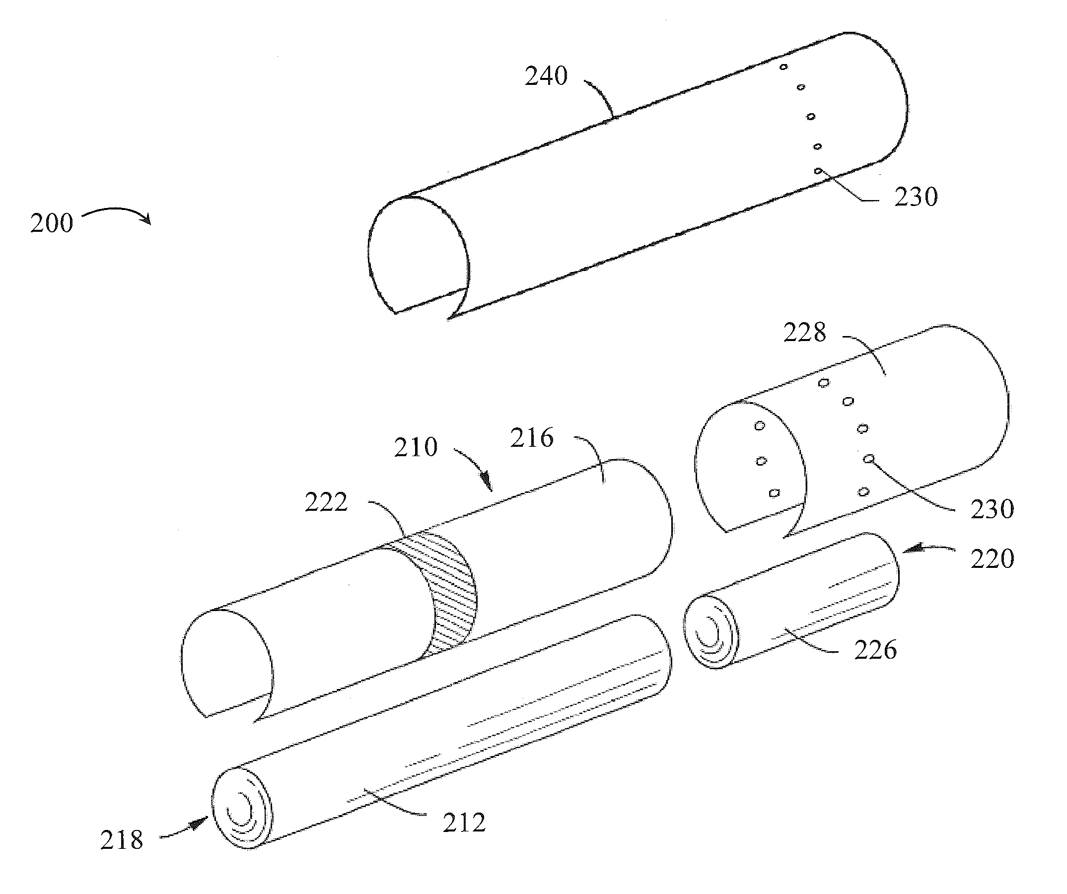
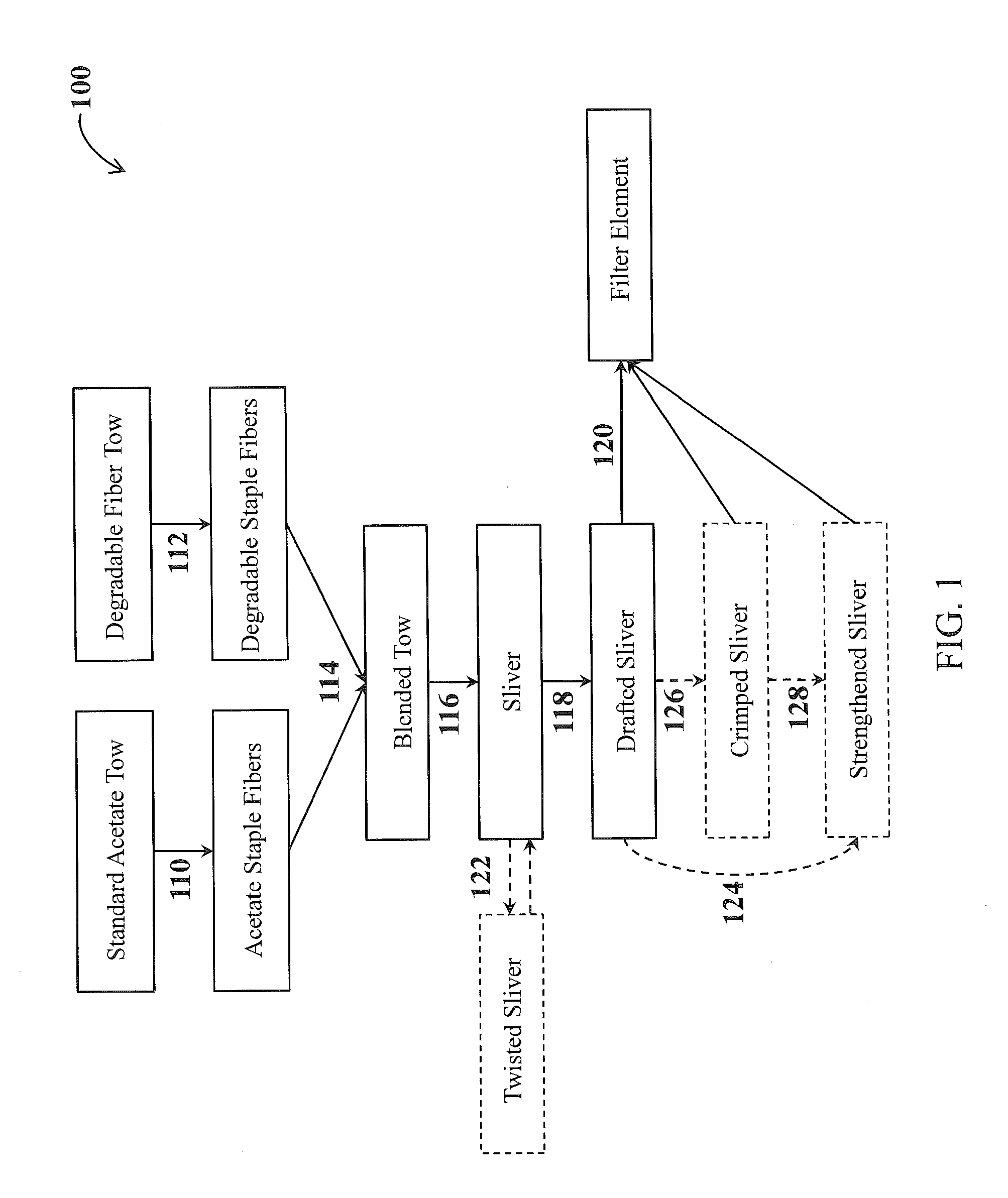
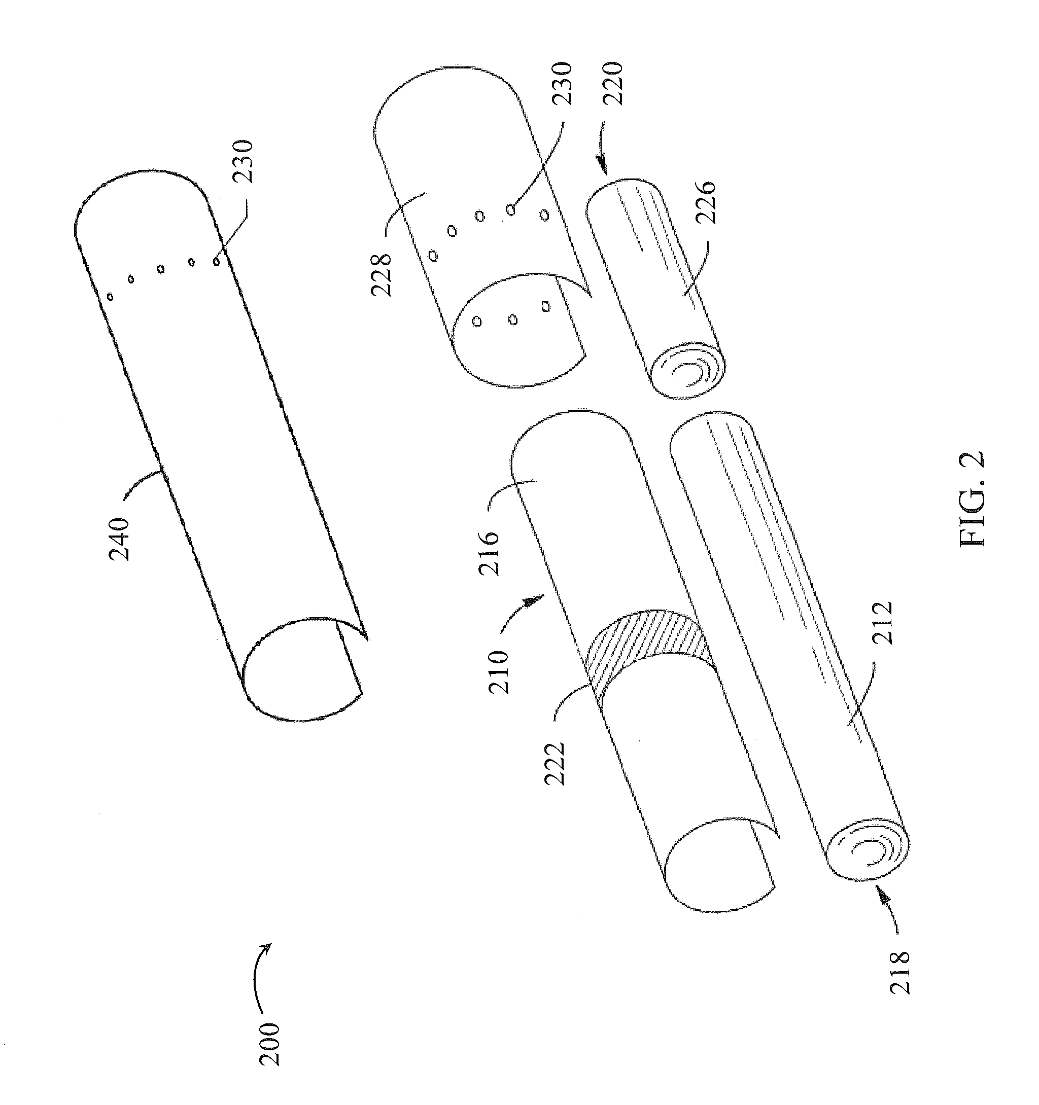
  • Mixed fiber sliver for use in the manufacture of cigarette filter elements
  • Mixed fiber sliver for use in the manufacture of cigarette filter elements
  • Mixed fiber sliver for use in the manufacture of cigarette filter elements

Examples


example 1

Sliver Preparation

[0072]a) Cutting

[0073]Acetate tow (40,000 denier, 3.0 dpf, supplied by Eastman Chemical Company) and rayon tow (1.5 million denier, 3.0 dpf, supplied by Lenzing) are separately cut into 7 inch staple fibers. The staple fibers are combined in a 1:1 ratio by hand blending.

[0074]b) Blending / Carding

[0075]The blended staple fibers are fed in 1 lb increments to a mini card feed apron and processed through a roller top card (Carolina Specialty TTC Mini Card). The resulting sliver is a 90-100 grain per yard sliver having a denier of about 57,000-64,000 denier.

[0076]The sliver at this point has a breaking strength of about 1 pound at maximum load. It is noted that this data is based on an unoptimized sliver. As described in the present application, there are numerous ways of increasing the strength, such as by twisting the sliver or by inserting a fiber along the length of the sliver. Further, the carding method can be optimized in certain embodiments to provide a sliver ha...

example 2

Sheath-Core Production

[0079]As described above, one means for strengthening a sliver according to the invention is to insert another type of material so as to produce a product having a sheath-core type structure.

[0080]a) Insertion of Cellulose Acetate Yarn

[0081]A 10,000 denier textured cellulose acetate yarn is fed into the pin drafting unit so as to provide the yarn as a core within the drafted sliver. It is noted that, again, the drafting step was not optimized and thus, the same type of inhomogeneous product was produced and the sheath-core drafted sliver was uneven. The strengthened sliver exhibited a breaking strength of 16 lbs.

[0082]b) Insertion of Kevlar

[0083]A 24.0 denier / 3 dpf, 100% spun KEVLAR™ (poly-paraphenylene terephthalamide) is fed into the carding unit so as to provide the KEVLARTM as a core within the sliver. The strengthened sliver exhibited a breaking strength of 10 pounds.


PUM

PropertyMeasurementUnit
Fractionaaaaaaaaaa
Linear densityaaaaaaaaaa

Abstract

Smoking articles including filter elements formed from two or more fibrous inputs with different physical properties are provided. The two or more fibrous inputs are provided in the form of staple fibers, which are at least partially entangled with each other to form a mixed fiber sliver. The mixed fiber sliver includes a first plurality of cellulose acetate staple fibers blended with a second plurality of staple fibers comprising a polymeric material different from the first plurality of staple fibers, such as staple fibers of a degradable polymeric material. The entangled fibers of the mixed fiber sliver may be sufficiently separated from one another such that blooming operations typically required in filter element production may not be necessary prior to incorporating the mixed fiber sliver into a filter element. Related methods, apparatuses and mixed fiber products are also provided by the disclosure.

Description

FIELD OF THE DISCLOSURE[0001]The present disclosure relates to products made or derived from tobacco or other smokable material that are intended for human consumption. In particular, the disclosure relates to filter elements for smoking articles such as cigarettes, and related methods and apparatuses for producing filter elements.BACKGROUND[0002]Popular smoking articles, such as cigarettes, may have a substantially cylindrical rod-shaped structure and may include a charge, roll or column of smokable material, such as shredded tobacco (e.g., in cut filler form), surrounded by a paper wrapper, thereby forming a so-called “smokable rod” or “tobacco rod.” Normally, a cigarette has a cylindrical filter element aligned in an end-to-end relationship with the tobacco rod. Typically, a filter element comprises plasticized cellulose acetate tow circumscribed by a paper material known as “plug wrap.” Typically, the filter element is attached to one end of the tobacco rod using a circumscribin...

Claims


Application Information

Patent Timeline
IPC IPC(8): A24D3/06A24D3/02D02G1/00D01G13/00D01H5/00
CPCA24D3/068A24D3/0204A24D3/0212A24D3/063A24D3/10A24D3/14D01G13/00D01H5/00D02G1/00
Inventor SEBASTIAN, ANDRIES DON
Owner R J REYNOLDS TOBACCO COMPANY
Learn More