Light module and corresponding modular light system

Inactive Publication Date: 2014-01-23
CHROMLECH
View PDF1 Cites 7 Cited by
  • Summary
  • Abstract
  • Description
  • Claims
  • Application Information

AI Technical Summary

Benefits of technology

The patent describes a light device that can be easily assembled with other identical devices to create visual effects and light at different scales. This allows for the creation of customizable and environmentally-adapted lighting systems. The technical effect is greater flexibility and integration into the environment in which the light devices are assembled.

Problems solved by technology

However, it is still difficult to drive light-emitting diodes with a view to obtaining a fine, linear dimming curve.
Besides, owing to the technology used, diodes constitute highly blinding sources of light, with a very marked hot point.
However, in terms of lighting or illumination, these display walls emit only a low level of radiosity (in other words, they emit only weak, highly scattered light).
In addition, the installation and dismantling of these display walls, as well as their transportation, remain relatively complex.
There also exist known ways of making walls of projectors but, in this type of installation, the amount of space required and shape of the assembled projectors (the projectors are mostly round) do not enable the display of images.
It is thus impossible at the present time to make a wall of projectors cohabit with a banner.
Now such walls are not capable of carrying out image displays, i.e. controlling the light intensity of the light-emitting diodes also at low levels (typically less than one milliwatt).
No device presently offers the possibility of carrying out the light projector function, requiring “high-level” control of the light intensity (of the order of one watt or about ten watts) and the display screen function requiring a “low-level” control of the light intensity (of the order of one milliwatt or even one microwatt), together with the capability to pass constantly from one function to the other along a fine and linear dimming curve.
Besides, such light devices are relatively light-weight devices.
In addition, such a light device with light-emitting diodes is simple and costs little to implement and / or put to use.
This is a generally undesirable phenomenon that is present when a large number of light sources are assembled and driven simultaneously.

Method used


Image

  • Light module and corresponding modular light system
  • Light module and corresponding modular light system
  • Light module and corresponding modular light system

Examples


Embodiment Construction

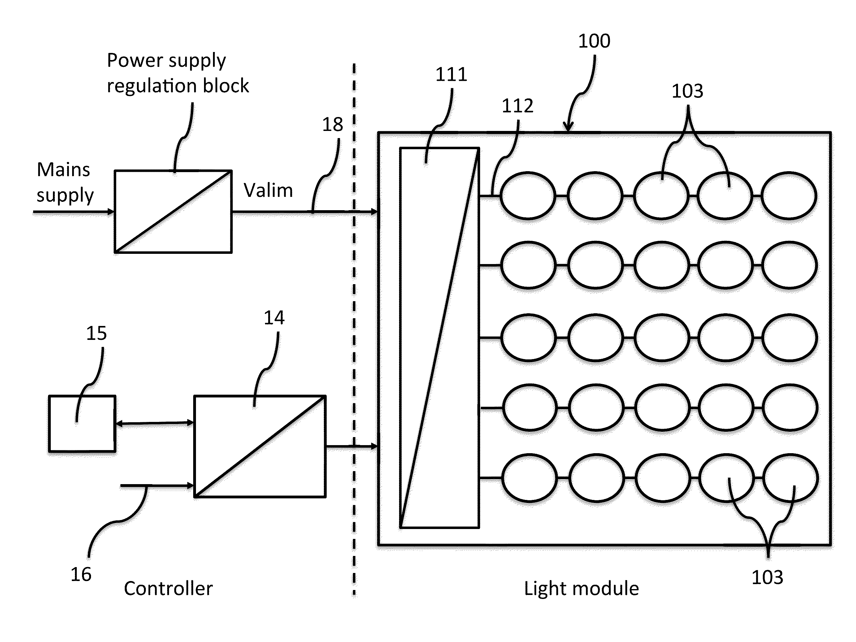
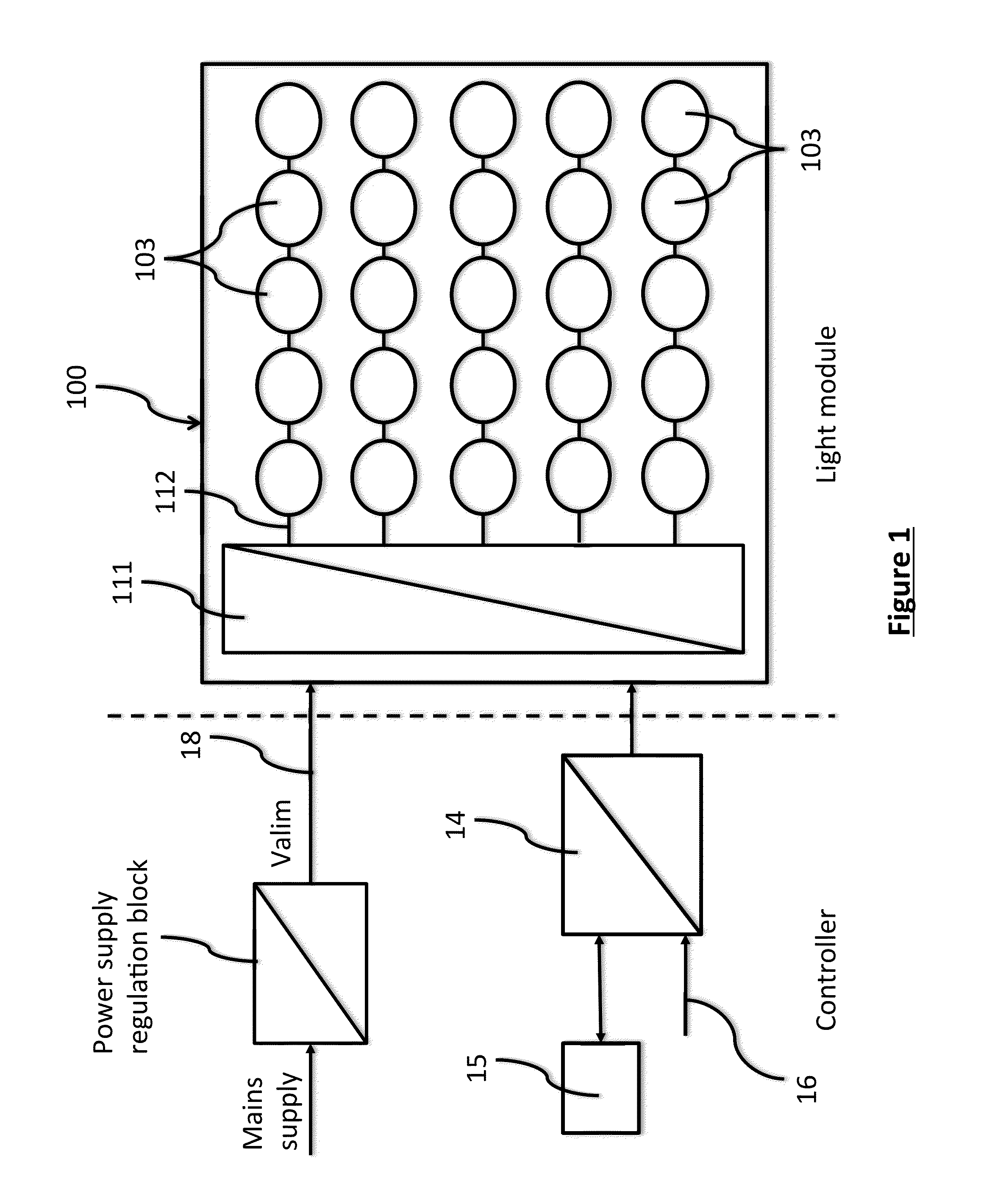
[0088]The general principle of an embodiment of the invention therefore relies on a wholly novel and inventive approach to a device or module with light-emitting diodes which, alone or in combination with one or more other modules, can form a lighting projector. The light intensity of the diodes can be adjusted with relative precision so as to use the assembling of the modules in a video screen.

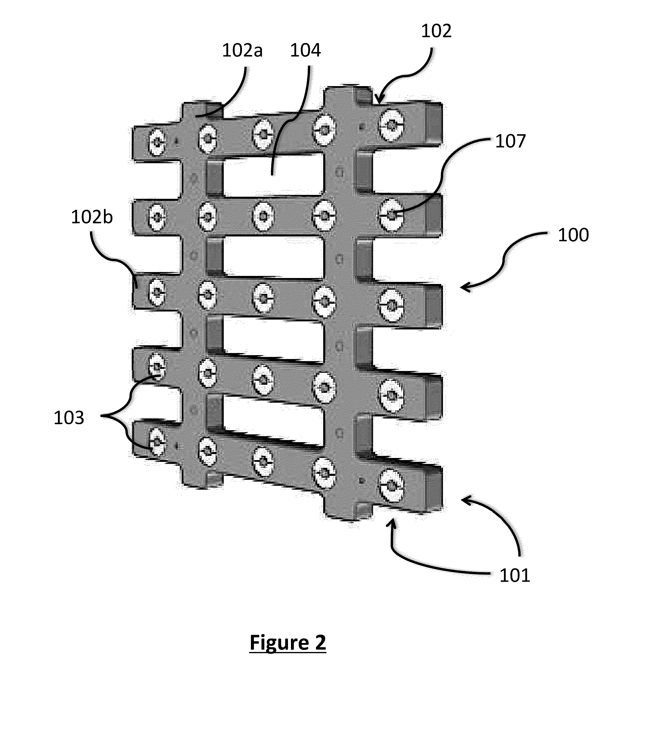
[0089]The assembling of the light modules is done with variable geometry, thus offering optimal flexibility and numerous possibilities of shapes of projectors and of the light beams produced. It also allows for greater creativity in the production of visual and light effects.

[0090]A more detailed description is now provided of an exemplary embodiment of the invention.

[0091]The light device according to an embodiment of the invention comprises a set of light sources, in this case light-emitting diodes, or LED lamps, organized in the form of a matrix of diodes sized N×M (N rows and M columns).

[...


PUM


Abstract

A light module is proposed, which includes a frame bearing a plurality of light sources disposed in a matrix arrangement and capable of forming a corresponding number of light points. The frame is configured for assembly with at least one other frame of an identical module, so as to enable juxtaposing and simultaneously driving a predetermined set of light modules. A modular light system is also proposed, which includes an assembly of a plurality of light modules.

Description

CROSS-REFERENCE TO RELATED APPLICATIONS[0001]None.STATEMENT REGARDING FEDERALLY SPONSORED RESEARCH OR DEVELOPMENT[0002]None.THE NAMES OF PARTIES TO A JOINT RESEARCH AGREEMENT[0003]None.FIELD OF THE DISCLOSURE[0004]The present disclosure generally pertains to apparatuses for cultural shows and events (such as concerts, theater, etc.) television, cinema, architectural lighting, discotheques, sports events, event coverage, organized events (advertising events, for example for shop windows or for decorating building facades).[0005]The disclosure pertains more particularly to the light modules implemented in such events and to the corresponding light modules.[0006]The disclosure can also be adapted without limitations to any type of internal or external environment.BACKGROUND OF THE DISCLOSURE[0007]Stage and scenic equipment is one of the keys to the success of a show.[0008]Stage lighting, especially lighting effects, play a role in the creativity and enhancement of a show, a scene or an...

Claims


Application Information

Patent Timeline
IPC IPC(8): G03B21/20
CPCG03B21/2053F21S2/005G09F9/33G09G2300/026G09G3/3426F21Y2105/10F21Y2115/10
Inventor VILLEFLOSE, BASTIANANTON RIOJA, JULIENGAILLY, ALEXANDRE
Owner CHROMLECH
Why Eureka
Try Eureka